


WAFER-TGL-U SBC
Page 48
4.4
M.2 Module Installation
To install an M.2 module, please follow the steps below.
Step 1:
Locate the M.2 module slot. See
Chapter 3
.
Step 2:
Remove the retention screw secured on the motherboard.
Step 3:
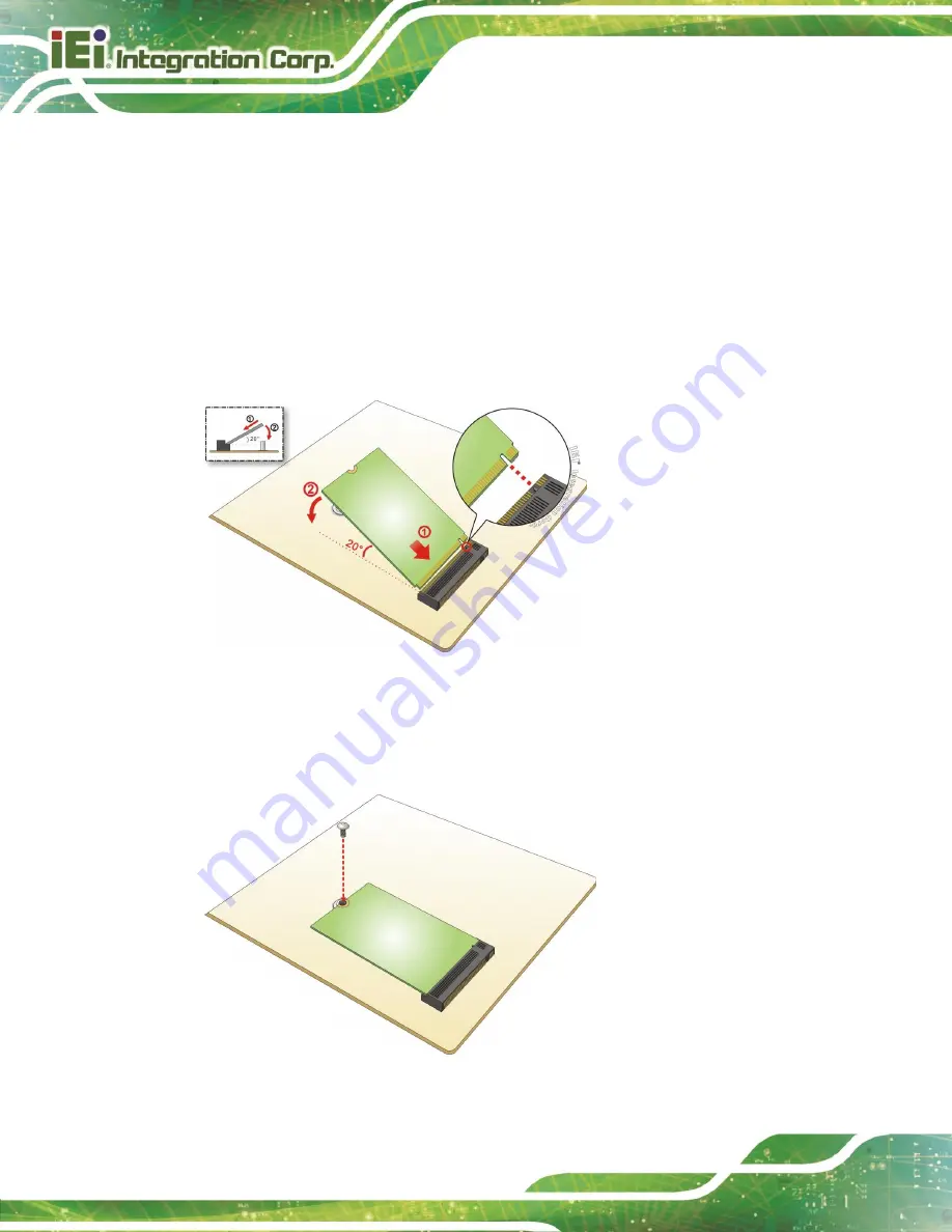
Line up the notch on the module with the notch on the slot. Slide the M.2 module
into the socket at an angle of about 20º (
).
Figure 4-2: Inserting the M.2 Module into the Slot at an Angle
Step 4:
Secure the M.2 module with the previously removed retention screw
).
Figure 4-3: Securing the M.2 Module
Содержание WAFER-TGL-U
Страница 2: ...WAFER TGL U SBC Page II MODEL NAME Revision Date Version Changes July 11 2022 1 00 Initial release...
Страница 11: ...WAFER TGL U SBC Page 1 Chapter 1 1 Introduction...
Страница 15: ...WAFER TGL U SBC Page 5 1 5 Dimensions The dimensions of the board are listed below Figure 1 3 Dimensions mm...
Страница 19: ...WAFER TGL U SBC Page 9 Chapter 2 2 Unpacking...
Страница 23: ...WAFER TGL U SBC Page 13 Chapter 3 3 Connectors...
Страница 54: ...WAFER TGL U SBC Page 44 Chapter 4 4 Installation...
Страница 69: ...WAFER TGL U SBC Page 59 Chapter 5 5 Software Drivers...
Страница 72: ...WAFER TGL U SBC Page 62 Appendix A A Regulatory Compliance...
Страница 74: ...WAFER TGL U SBC Page 64 B Product Disposal Appendix B...
Страница 76: ...WAFER TGL U SBC Page 66 Appendix C C Digital I O Interface...
Страница 79: ...WAFER TGL U SBC Page 69 Appendix D D Watchdog Timer...
Страница 82: ...WAFER TGL U SBC Page 72 Appendix E E Error Beep Code...
Страница 84: ...WAFER TGL U SBC Page 74 Appendix F F Hazardous Materials Disclosure...


