


WAFER-PV-D4251/D5251/N4551 SBC
Page 51
Step 2:
Align the VGA connector
. Align the male DB-15 connector on the VGA screen
cable with the female DB-15 connector on the external peripheral interface.
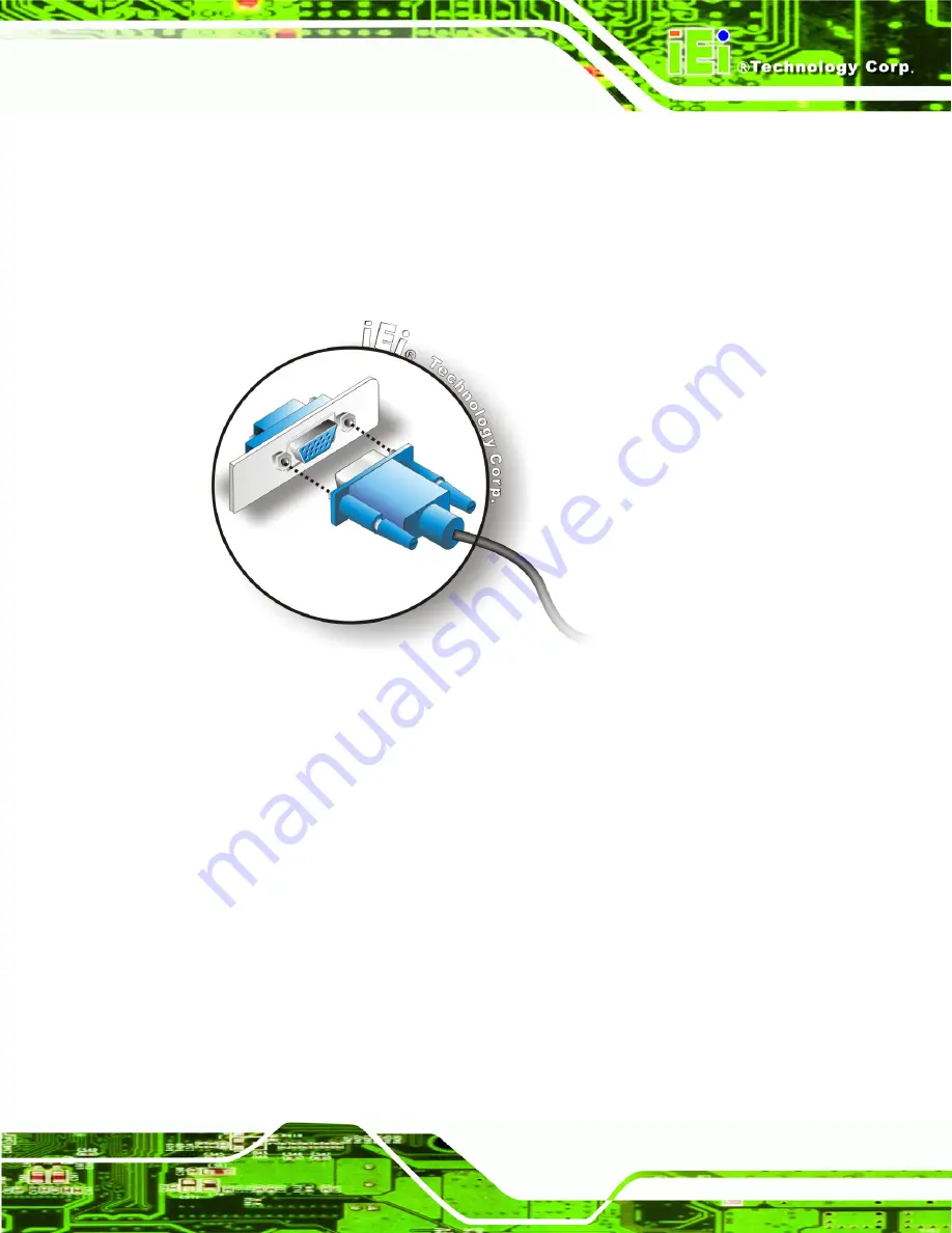
Step 3:
Insert the VGA connector
.
Once the connectors are properly aligned with the
insert the male connector from the VGA screen into the female connector on the
WAFER-PV-D4251/D5251/N4551. See Figure 4-13.
Figure 4-13: VGA Connector
Step 4:
Secure the connector
. Secure the DB-15 VGA connector from the VGA
monitor to the external interface by tightening the two retention screws on either
side of the connector.
Step 0:
4.8 Software Installation
All the drivers for the WAFER-PV-D4251/D5251/N4551 are on the CD that came with the
system. To install the drivers, please follow the steps below.
Step 1:
Insert the CD into a CD drive connected to the system.
Содержание WAFER-PV-D4251
Страница 14: ......
Страница 15: ...WAFER PV D4251 D5251 N4551 SBC Page 1 Chapter 1 1 Introduction...
Страница 22: ...WAFER PV D4251 D5251 N4551 SBC Page 8 Chapter 2 2 Packing List...
Страница 26: ...WAFER PV D4251 D5251 N4551 SBC Page 12 Chapter 3 3 Connector Pinouts...
Страница 47: ...WAFER PV D4251 D5251 N4551 SBC Page 33 Figure 3 22 VGA Connector...
Страница 48: ...WAFER PV D4251 D5251 N4551 SBC Page 34 Chapter 4 4 Installation...
Страница 68: ...WAFER PV D4251 D5251 N4551 SBC Page 54 Chapter 5 5 BIOS...
Страница 93: ...WAFER PV D4251 D5251 N4551 SBC Page 79 Appendix A A BIOS Options...
Страница 96: ...WAFER PV D4251 D5251 N4551 SBC Page 82 Appendix B B One Key Recovery...
Страница 124: ...WAFER PV D4251 D5251 N4551 SBC Page 110 Appendix C C Terminology...
Страница 128: ...WAFER PV D4251 D5251 N4551 SBC Page 114 Appendix D D Hazardous Materials Disclosure...


