


WAFER-AL SBC
Page 64
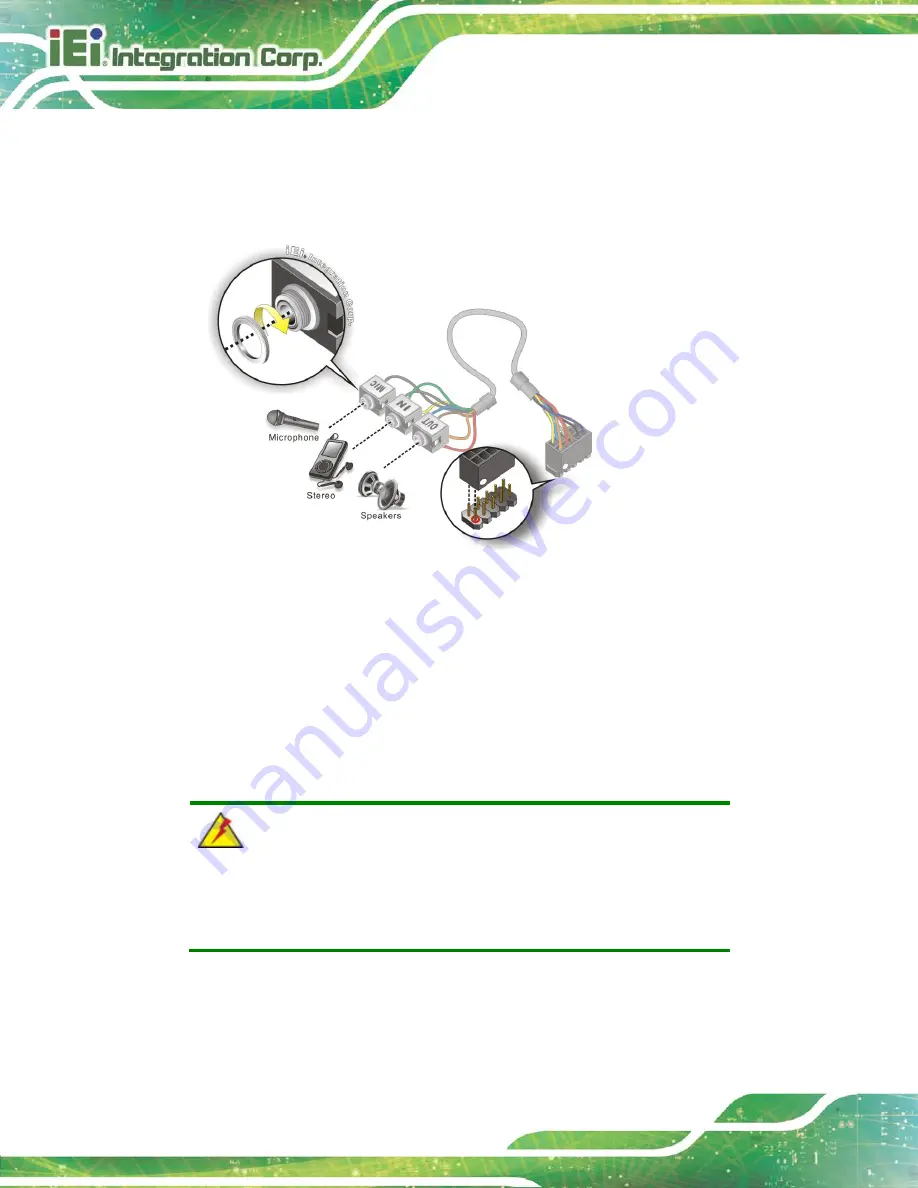
Step 2:
Align pin 1
. Align pin 1 on the on-board connector with pin 1 on the audio kit
connector. Pin 1 on the audio kit connector is indicated with a white dot. See
Figure 4-18: Audio Kit Cable Connection
Step 3:
Connect the audio devices
. Connect speakers to the line-out audio jack.
Connect the output of an audio device to the line-in audio jack. Connect a
microphone to the mic-in audio jack.
Step 0:
4.9.2 AT Power Connection
Follow the instructions below to connect the WAFER-AL to an AT power supply.
WARNING:
Disconnect the power supply power cord from its AC power source to
prevent a sudden power surge to the WAFER-AL.
Step 1:
Locate the power cable
. The power cable is shown in the packing list in
Chapter 2
.
Содержание WAFER-AL
Страница 14: ......
Страница 15: ...WAFER AL SBC Page 1 Chapter 1 1 Introduction...
Страница 19: ...WAFER AL SBC Page 5 Figure 1 3 Connectors Solder Side...
Страница 24: ...WAFER AL SBC Page 10 Chapter 2 2 Unpacking...
Страница 28: ...WAFER AL SBC Page 14 Chapter 3 3 Connectors...
Страница 61: ...WAFER AL SBC Page 47 Chapter 4 4 Installation...
Страница 82: ...WAFER AL SBC Page 68 Chapter 5 5 BIOS...
Страница 120: ...WAFER AL SBC Page 106 Chapter 6 6 Software Drivers...
Страница 124: ...WAFER AL SBC Page 110 Appendix A A Regulatory Compliance...
Страница 126: ...WAFER AL SBC Page 112 B Product Disposal Appendix B...
Страница 128: ...WAFER AL SBC Page 114 Appendix C C BIOS Menu Options...
Страница 131: ...WAFER AL SBC Page 117 Appendix D D Digital I O Interface...
Страница 134: ...WAFER AL SBC Page 120 Appendix E E Watchdog Timer...
Страница 137: ...WAFER AL SBC Page 123 Appendix F F Hazardous Materials Disclosure...


