


WAFER-AL SBC
Page 50
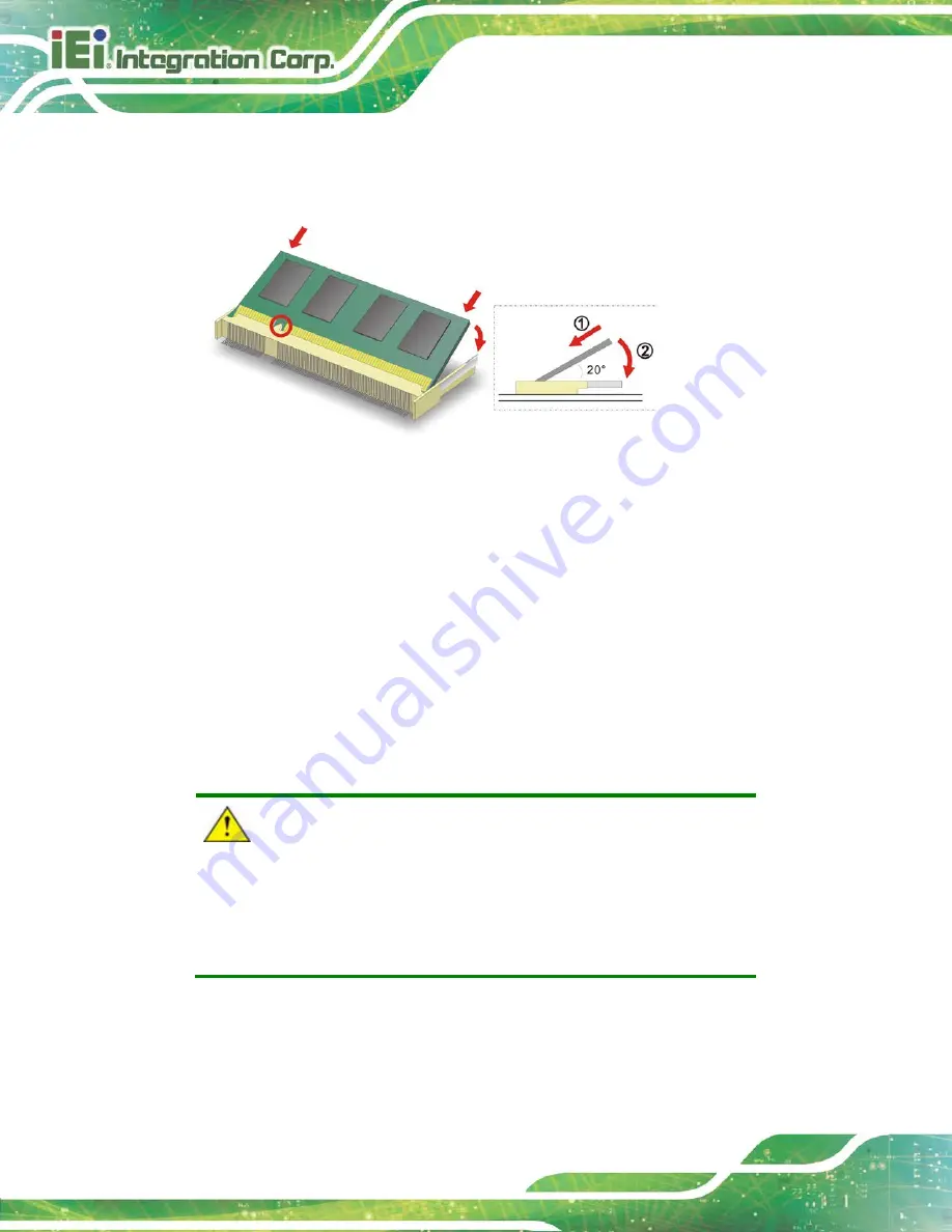
4.3 SO-DIMM Installation
To install an SO-DIMM, please follow the steps below and refer to
Figure 4-1: SO-DIMM Installation
Step 1:
Locate the SO-DIMM socket
. Place the board on an anti-static mat.
Step 2:
Align the SO-DIMM with the socket
. Align the notch on the memory with the
notch on the memory socket.
Step 3:
Insert the SO-DIMM
. Push the memory in at a 20º angle. (See
Step 4:
Seat the SO-DIMM
. Gently push downwards and the arms clip into place. (See
4.4 mSATA Module Installation
CAUTION:
If an mSATA module is installed in the mSATA slot (MINI-PCIE1), the
SATA port 2 (SATA2) will be disabled. Choose either the SATA2
connector or the mSATA module for storage.
The full-size/half-size PCIe Mini card slot (MINI-PCIE1) allows installation of an mSATA
module. To install an mSATA module, please follow the steps below.
Содержание WAFER-AL
Страница 14: ......
Страница 15: ...WAFER AL SBC Page 1 Chapter 1 1 Introduction...
Страница 19: ...WAFER AL SBC Page 5 Figure 1 3 Connectors Solder Side...
Страница 24: ...WAFER AL SBC Page 10 Chapter 2 2 Unpacking...
Страница 28: ...WAFER AL SBC Page 14 Chapter 3 3 Connectors...
Страница 61: ...WAFER AL SBC Page 47 Chapter 4 4 Installation...
Страница 82: ...WAFER AL SBC Page 68 Chapter 5 5 BIOS...
Страница 120: ...WAFER AL SBC Page 106 Chapter 6 6 Software Drivers...
Страница 124: ...WAFER AL SBC Page 110 Appendix A A Regulatory Compliance...
Страница 126: ...WAFER AL SBC Page 112 B Product Disposal Appendix B...
Страница 128: ...WAFER AL SBC Page 114 Appendix C C BIOS Menu Options...
Страница 131: ...WAFER AL SBC Page 117 Appendix D D Digital I O Interface...
Страница 134: ...WAFER AL SBC Page 120 Appendix E E Watchdog Timer...
Страница 137: ...WAFER AL SBC Page 123 Appendix F F Hazardous Materials Disclosure...


