background image


POC-W22A-H81 Medical Panel PC 

Page 51

4.1 Available Software Drivers 

 NOTE: 

The contents of the driver folder may vary throughout the life cycle of 

the product and is subject to change without prior notice. Visit the IEI 

website or contact technical support for the latest updates. 

All the drivers for the POC-W22A-H81 are on the utility CD that came with the system. To 

install the drivers, please follow the steps below. 

Step 1: 

Insert the CD into a CD drive connected to the system.   

Step 2: 

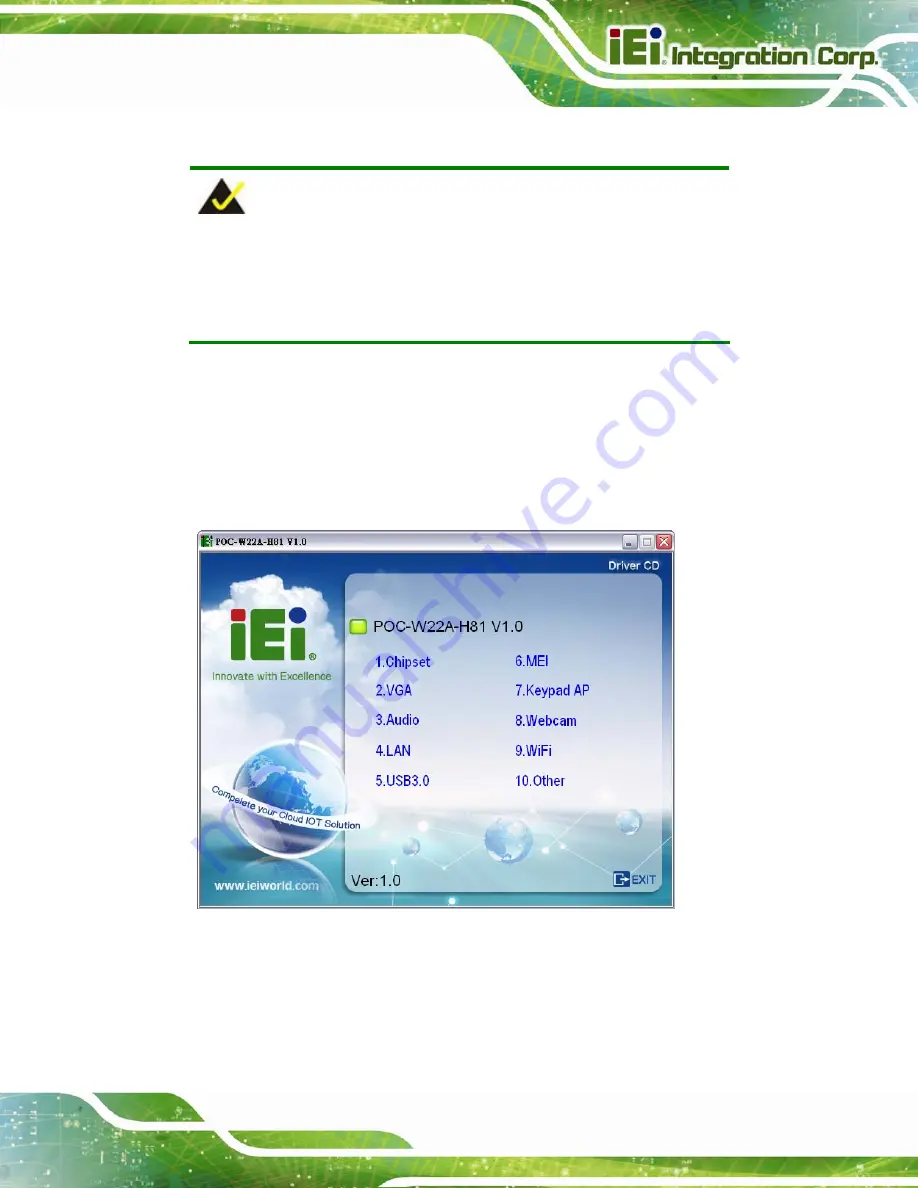
The driver main menu with a list of available drivers appears (

Figure 4-1

). 


Figure 4-1: Available Drivers 

Step 3: 

Install all of the necessary drivers in this menu. 

Содержание POC-W22A-H81

Страница 1: ...User Manual POC W22A H81 MODEL 21 5 Medical Panel PC with 4th Generation Intel Dual Core CPU Touchscreen Anti bacteria Cover Dual USB 3 0 Dual GbE LAN RS 232 422 485 HDMI VGA Front IP 65 Rating and RoHS Rev 1 00 October 17 2016 User Manual ...

Страница 2: ...POC W22A H81 Medical Panel PC Page II Revision Date Version Changes October 17 2016 1 00 Initial release ...

Страница 3: ...ssibility of such damages This document contains proprietary information protected by copyright All rights are reserved No part of this manual may be reproduced by any mechanical electronic or other means in any form without prior written permission of the manufacturer TRADEMARKS All registered trademarks and product names mentioned herein are used for identification purposes only and may be trade...

Страница 4: ...duce the chance of losing data or damaging the product NOTE These messages inform the reader of essential but non critical information These messages should be read carefully as any directions or instructions contained therein can help avoid making mistakes HOT SURFACE This symbol indicates a hot surface that should not be touched without taking care OPERATING INSTRUCTION Follow operating instruct...

Страница 5: ...PACKING 15 2 2 PACKING LIST 16 2 3 OPTIONAL ITEMS 17 3 INSTALLATION 20 3 1 ANTI STATIC PRECAUTIONS 21 3 2 INSTALLATION PRECAUTIONS 21 3 3 INSTALLATION AND CONFIGURATION STEPS 22 3 4 REMOVING THE BACK COVER 22 3 5 HDD INSTALLATION 24 3 6 UPS BATTERY 26 3 7 HANDSET INSTALLATION OPTIONAL 27 3 7 1 Using VoIP Handset 28 3 8 HANDLE INSTALLATION OPTIONAL 31 3 8 1 Barcode Reader Installation 32 3 8 2 Read...

Страница 6: ...R INSTALLATION 50 4 1 AVAILABLE SOFTWARE DRIVERS 51 4 2 INTEL CHIPSET DRIVER 52 4 3 INTEL GRAPHICS DRIVER 52 4 4 AUDIO DRIVER 53 4 5 LAN DRIVER 54 4 6 USB 3 0 DRIVER 55 4 7 INTEL MANAGEMENT ENGINE 56 4 8 KEYPAD AP 57 4 9 WIRELESS LAN DRIVER 59 4 10 BLUETOOTH DRIVER 59 4 11 RFID DRIVER OPTIONAL 60 4 12 3 IN 1 COMBO READER DRIVER OPTIONAL 63 4 12 1 SCR Driver 63 4 12 2 MSR Driver 67 4 12 3 Fingerpri...

Страница 7: ... 3 8 iWDD H W Monitor 90 5 3 8 1 Smart Fan Mode Configuration 91 5 3 9 Serial Port Console Redirection 93 5 3 10 IEI Feature 94 5 4 CHIPSET 95 5 4 1 PCH IO Configuration 95 5 4 1 1 PCI Express Configuration 96 5 4 1 2 PCH Azalia Configuration 97 5 4 2 System Agent SA Configuration 98 5 4 2 1 Graphics Configuration 99 5 4 2 2 Memory Configuration 101 5 5 BOOT 101 5 6 SECURITY 103 5 7 SAVE EXIT 104 ...

Страница 8: ...5 B SAFETY PRECAUTIONS 120 B 1 SAFETY PRECAUTIONS 121 B 1 1 General Safety Precautions 121 B 1 2 Anti static Precautions 122 B 1 3 Product Disposal 123 B 1 4 Classification 124 B 2 MAINTENANCE AND CLEANING PRECAUTIONS 124 B 2 1 Maintenance and Cleaning 124 B 2 2 Cleaning Tools 125 C EMC TEST SUMMARY 126 D BIOS MENU OPTIONS 132 E WATCHDOG TIMER 135 F HAZARDOUS MATERIALS DISCLOSURE 138 ...

Страница 9: ... Figure 3 7 HDD Installation 26 Figure 3 8 Handset Holder Retention Screws 27 Figure 3 9 Handset Installation 28 Figure 3 10 Handset Driver Folder 28 Figure 3 11 Handset Driver Installation 29 Figure 3 12 Allow API Access 29 Figure 3 13 Manage Program Access to Skype 30 Figure 3 14 Handle Installation 32 Figure 3 15 Insert Barcode Reader Set 33 Figure 3 16 Install and Connect Barcode Reader Set 33...

Страница 10: ...ftware Install Wizard 52 Figure 4 3 Intel Graphics Driver InstallShield Wizard 53 Figure 4 4 Realtek HD Audio Driver InstallShield Wizard 54 Figure 4 5 LAN Driver Install Wizard 55 Figure 4 6 USB 3 0 Driver Install Wizard 56 Figure 4 7 Intel ME Components Install Wizard 57 Figure 4 8 Keypad Setup Wizard 58 Figure 4 9 Keypad AP 58 Figure 4 10 Wireless LAN InstallShield Wizard 59 Figure 4 11 Bluetoo...

Страница 11: ...gure 4 27 Driver Installation Complete Window 69 Figure 4 28 Device Manager Window MSR Device 70 Figure 4 29 Fingerprint Reader Driver Folder 71 Figure 4 30 Fingerprint Reader Driver InstallShield Wizard 71 Figure 4 31 Barcode Reader Driver Folder 72 Figure 4 32 Barcode Reader Driver Installation 72 Figure 4 33 Device Manager Window Barcode Reader Device 73 Figure 6 1 System Fan Retention Screws a...

Страница 12: ...XII List of Tables Table 1 1 Model Variations 3 Table 1 2 Touch Button Functions 6 Table 1 3 System Specifications 12 Table 3 1 Handset Button Functions 31 Table 3 2 RS 232 422 485 Serial Port Pinouts 40 Table 5 1 BIOS Navigation Keys 76 ...

Страница 13: ...nu 11 iWDD H W Monitor 90 BIOS Menu 12 Smart Fan Mode Configuration 91 BIOS Menu 13 Serial Port Console Redirection 93 BIOS Menu 14 IEI Feature 94 BIOS Menu 15 Chipset 95 BIOS Menu 16 PCH IO Configuration 95 BIOS Menu 17 PCI Express Configuration 96 BIOS Menu 18 PCH Azalia Configuration 97 BIOS Menu 19 System Agent SA Configuration 98 BIOS Menu 20 Graphics Configuration 99 BIOS Menu 21 Memory Conf...

Страница 14: ......

Страница 15: ...POC W22A H81 Medical Panel PC Page 1 1 Introduction Chapter 1 ...

Страница 16: ...ata throughputs with reduced bottlenecks and fast system access Dual display support is provided via the HDMI port or the VGA port One RS 232 422 485 serial port two USB 3 0 ports and four USB 2 0 ports provide simplified connectivity to a variety of external peripheral devices Wi Fi 802 11a b g n ac high speed wireless and two RJ 45 GbE connectors allow for smooth connection of the system to an e...

Страница 17: ...ipment to the signal input part or signal output part configure a medical system and is therefore responsible that the system complies with current version of the requirements of the system standard IEC 60601 1 1 If in doubt consult the technical service department or your local representative 1 2 Model Variations There are three models in the POC W22A H81 series All models are preinstalled with t...

Страница 18: ...creen Two PCIe GbE RJ 45 connectors and Wi Fi 802 11a b g n ac high speed wireless Two internal 3 W speakers Four USB 2 0 ports and two USB 3 0 ports 12 V 28 V wide range DC power input Optional internal 54 W battery module One RS 232 422 485 serial port by D sub 9 connector IP 65 compliant front panel Optional Mifare RFID reader Optional 3 in 1 card reader supports magnetic stripe card smart card...

Страница 19: ...PS battery can provide backup power for 30 minutes in idle mode and the maximum discharge voltage is 3 7 A The POC W22A H81 will shutdown when the discharge voltage is over 3 7 A The status descriptions of the battery LED indicator are listed below Solid amber the battery is being charged Solid blue the system is using battery power or the battery is fully charged Blinking amber the battery is low...

Страница 20: ... 100 Volume down Volume up Touch lock for cleaning long press for 3 seconds to lock or unlock the touch function of the screen The touch buttons blink when the touch function is locked The lock will be automatically disabled after 2 minutes Lock or unlock the touch buttons long press for 3 seconds to lock or unlock the touch buttons The touch buttons blink when the touch buttons are locked Power o...

Страница 21: ...ng a PCIe Mini I O card Figure 1 4 Side View 1 6 Bottom Panel The bottom panel of the POC W22A H81 has the following connectors and switches Figure 1 5 1 x 12 V 28 V DC input power jack 1 x RS 232 422 485 DB 9 connector 1 x Barcode reader RJ 11connector 2 x GbE RJ 45 connector 2 x USB 3 0 connector 2 x USB 2 0 connector 1 x HDMI connector 1 x VGA connector 1 x AT ATX switch 1 x Power button 1 x Re...

Страница 22: ...POC W22A H81 Medical Panel PC Page 8 Figure 1 5 Bottom Panel 1 7 Rear Panel The rear panel provides access to retention screw holes that support VESA mounting See Figure 1 6 Figure 1 6 Rear View ...

Страница 23: ...z dual channel DDR3 SO DIMM slots preinstalled with two 2 GB SDRAM system max 16 GB Storage One PCIe Mini card slot for mSATA module installation ATO One 2 5 SATA HDD bay Auto dimming Built in ambient light sensor for panel brightness adjustment LCD and Touchscreen LCD Size 21 5 16 9 Max Resolution 1920 W x 1080 H Brightness cd m2 250 Contrast Ratio 1000 1 LCD Color 16 7M Pixel Pitch mm 0 24825 H ...

Страница 24: ...attery Optional 3550 mAH 54 W internal Li Ion battery with LED indicator Remote Management One iRIS 2400 slot supports iRIS remote management module RFID Reader Optional Mifare 13 56 MHz card reader with LED indicator Card Reader Optional 3 in 1 card reader supports magnetic stripe card smart card and fingerprint Handle Optional handle with without 1D 2D barcode reader and reading light Connectors...

Страница 25: ...cators 2 light battery status LED indicator optional RFID LED indicator optional Physical Construction Material PC ABS plastic with anti bacterial material VESA Mount 100 mm x 100 mm Dimensions W x H x D 542 5 mm x 349 5 mm x 52 mm Net Weight 7 3 kg Environment Temperature 20ºC 60ºC Humidity 10 95 non condensing Transportation Storage Pressure 700 hPa 1060 hPa Temperature 0ºC 40ºC Humidity 10 95 n...

Страница 26: ...Level IP 65 compliant front panel Safety EMC CE FCC class B part 18 UL 60601 1 EN 60601 1 Power Power Supply 120 W medical grade power adapter FSP PMP120 13 2 Input 100 V AC 240 V AC 47 Hz 63 Hz 1 4 A 0 6 A Output 120 W Max 19 V 6 32 A Power Requirement 12 V 28 V DC Table 1 3 System Specifications ...

Страница 27: ...POC W22A H81 Medical Panel PC Page 13 1 9 Dimensions The POC W22A H81 dimensions are shown below Figure 1 7 Dimensions mm ...

Страница 28: ...POC W22A H81 Medical Panel PC Page 14 2 Unpacking Chapter 2 ...

Страница 29: ...ring the installation process Step 1 Use box cutters a knife or a sharp pair of scissors that seals the top side of the external second box Step 2 Open the external second box Step 3 Use box cutters a knife or a sharp pair of scissors that seals the top side of the internal first box Step 4 Lift the monitor out of the boxes Step 5 Remove both polystyrene ends one from each side Step 6 Pull the pla...

Страница 30: ...ed from or contact an IEI sales representative directly by sending an email to 32sales ieiworld com The POC W22A H81 medical panel PC is shipped with the following components Quantity Item Image 1 POC W22A H81 medical panel PC 1 Medical grade power adapter 120 W 19 V DC output P N 63040 010120 010 RS 1 Power cord P N 32702 000200 100 RS 4 Pan head screw M3 5 for HDD installation P N 44043 030051 R...

Страница 31: ... 3 Optional Items The following are optional components which may be separately purchased Item and Part Number Image 3 in 1 reader smart card magnetic card fingerprint P N MEDP CR R10 Handle P N MEDP HD R10 Handle with 1D 2D barcode reader and reading light P N MEDP HD BR R10 ...

Страница 32: ...t Number Image Handset USB interface and holder P N MEDP HS R10 Cable cover P N POCP CC01 R10 EZ Stand with cabling hole VESA 100 P N MEDP EZS R10 VESA 100 wall mount kit four M3 6 screws included P N AFLWK 19B Arm P N ARM 31 RS Stand P N STAND A21 R10 ...

Страница 33: ...ble to order P N MEDP TPM R10 14 8 V 3550 mAH Li ion battery Getac BAT003 4S1P3550 0 assemble to order P N MEDP BAT R10 Mifare RFID reader compliant with ISO 14443A ISO 14443B and ISO 15693 protocols assemble to order P N MEDP MF RFID R10 If any of these items are missing or damaged contact the distributor or sales representative immediately ...

Страница 34: ...POC W22A H81 Medical Panel PC Page 20 3 Installation Chapter 3 ...

Страница 35: ...ring a simple anti static wristband can help to prevent ESD from damaging the board Self grounding Before handling the board touch any grounded conducting material During the time the board is handled frequently touch any conducting materials that are connected to the ground Use an anti static pad When configuring the POC W22A H81 place it on an anti static pad This reduces the possibility of ESD ...

Страница 36: ... anti static wristband 3 3 Installation and Configuration Steps The following installation steps must be followed Step 1 Unpack the medical panel PC Step 2 Install a HDD Step 3 Install necessary accessories handset handle or combo reader Step 4 Configure the system Step 5 Connect peripheral devices to the medical panel PC Step 6 Mount the medical panel PC Step 0 3 4 Removing the Back Cover To acce...

Страница 37: ...e 3 1 Back Cover Retention Screws Step 2 The back cover is attached to the chassis through a magnetic force To remove the back cover grasp the back cover finger grips as shown in Figure 3 2 and lift the cover up Figure 3 2 Remove the Back Cover ...

Страница 38: ...ps below Step 1 Remove the back cover See Section 3 4 above Step 2 Remove the two HDD bracket retention screws Figure 3 3 and lift the HDD bracket off the panel PC Figure 3 3 HDD Bracket Retention Screws Step 3 Slide the bottom bracket to remove it from the HDD cover Figure 3 4 Figure 3 4 HDD Bottom Bracket Removal ...

Страница 39: ... of the HDD Insert four retention screws M3 5 into the bracket Figure 3 5 Figure 3 5 HDD Retention Screws Step 5 Slide the bottom bracket into the HDD cover Figure 3 6 Figure 3 6 HDD Cover Installation Step 6 Install the HDD into the POC W22A H81 by inserting and connecting the HDD to the SATA connectors Then secure the HDD bracket to the chassis with the previously removed retention screws See Fi...

Страница 40: ... on the front panel The LED status descriptions are described in Section 1 4 CAUTION The following precautions should be followed when using the battery Do not use battery power to boot up the POC W22A H81 Charge the battery with a voltage higher than 16 8 V Charging time from 30 to 100 o System off 3 hours o System on 2 hours Risk of explosion if battery is replaced by an incorrect type Only cert...

Страница 41: ...nd the holder please follow the instruction below Step 1 Locate the two retention screw holes for installing the handset holder on the rear panel Step 2 Secure the handset holder with the POC W22A H81 by two retention screws M3 8 flat head Figure 3 8 Handset Holder Retention Screws Step 3 Plug the handset cord into a USB connector on the bottom panel Step 4 Place the handset in the holder ...

Страница 42: ...o use the handset to place or receive a call via Skype please follow the steps below Step 1 Install the Skype program http www skype com en Step 2 Select Other from the list of the driver CD Double click the setup file in the POCP W22A HS R10_U 2000H folder to install the handset driver 475Figure 3 10 Figure 3 10 Handset Driver Folder ...

Страница 43: ...d Figure 3 11 to install the handset driver Figure 3 11 Handset Driver Installation Step 4 Launch Skype Press the Allow access button on Skype Figure 3 12 to allow handset API access Figure 3 12 Allow API Access API access can also be managed through Tools Options Advanced settings in Skype See Figure 3 13 ...

Страница 44: ... H81 Medical Panel PC Page 30 Figure 3 13 Manage Program Access to Skype Step 5 The user can now use Skype via the handset The function description of each button on the handset is listed in the following table ...

Страница 45: ... call activity scroll down through incoming and outgoing call history Active call handset speaker volume down Place answer or hang up a call Table 3 1 Handset Button Functions 3 8 Handle Installation Optional An optional handle can be installed on the POC W22A H81 for the user to easily adjust the viewing angle and the position of the POC W22A H81 To install the handle please follow the instructio...

Страница 46: ...t with three levels of brightness To install the barcode reader set please follow the instruction below Step 1 Follow the instruction described above to install the handle Step 2 Insert the barcode reader set into the slot in the center of the handle To be able to insert the barcode reader the side with barcode reader must face toward the right side of the POC W22A H81 as shown in Figure 3 15 ...

Страница 47: ...ition Figure 3 16 Step 4 Connect the barcode reader cable to the RJ 11 connector on the bottom panel of the POC W22A H81 Figure 3 16 Figure 3 16 Install and Connect Barcode Reader Set Step 5 Install the driver for the barcode reader by following the instructions described in Section 4 13 Step 6 After driver installation is complete push the barcode reader button to trigger the barcode reader ...

Страница 48: ...hat the laser beam hits reflective surfaces such as mirrors etc Any changes at the device are forbidden these could cause a dangerous laser light 3 8 2 Reading Light The barcode reader is also equipped with a reading light with 3 level of brightness Push the reading light button to turn on or to toggle illumination brightness levels Figure 3 18 Reading Light ...

Страница 49: ...ombo Reader To install the combo reader to the POC W22A H81 please follow the steps below Step 1 Open the USB port cover on the side panel of the POC W22A H81 Secure the cover by rotating the cover and inserting the stub into the hole on the side panel Figure 3 20 USB Ports on the Side Panel Step 2 Align the USB connectors on the reader with the two USB connectors on the side panel of the POC W22A...

Страница 50: ...PC Page 36 Figure 3 21 Combo Reader Installation Step 4 Secure the combo reader to the system by inserting two retention screws M3x5L into the rear panel of the POC W22A H81 and tightening them Figure 3 22 Secure the Combo Reader ...

Страница 51: ...C W22A H81 may come with an optional RFID reader pre installed inside the bottom of the front panel To use the RFID reader follow the steps below Step 1 Install the RFID driver refer to Section 4 11 Step 2 Locate the IRFR 100 exe file in the following folder of the driver CD Docs 10 Other POCP MF RFID R10 RFID D490 Copy the IRFR 100 exe program to the desktop Figure 3 23 RFID Program Location Step...

Страница 52: ...dical Panel PC Page 38 Step 4 The IRFR 100 window appears 5Figure 3 25 Figure 3 25 IRFR Screen Step 5 Select the Find tags tab and click the Run button to enable the RFID reader 5Figure 3 26 Figure 3 26 IRFR Find Tags ...

Страница 53: ...r on the bottom of the front panel Figure 1 2 then remove it The card number will be shown in the UIDs column 5Figure 3 27 Figure 3 27 IRFR UIDs NOTE Please refer to the IRFR 100 user guide in the driver CD IRFR 100_AP_UserGuide pdf for detailed instruction on how to use the IRFR 100 ...

Страница 54: ...ow Pin RS 232 RS 422 RS 485 1 DCD TXD422 TXD485 2 RX TXD422 TXD485 3 TX RXD422 4 DTR RXD422 5 GND 6 DSR 7 RTS 8 CTS 9 RI Table 3 2 RS 232 422 485 Serial Port Pinouts 3 12 AT ATX Mode Selection AT or ATX power mode can be used on the POC W22A H81 The selection is made through an AT ATX switch located on the bottom panel Figure 3 28 Figure 3 28 AT ATX Switch Location 3 12 1 AT Power Mode With the AT...

Страница 55: ...for the user to easily manage cables To install the cable cover please follow the instruction below Step 1 Align the three tabs on the rear of the cable cover with the slots on the bottom panel of the POC W22A H81 Figure 3 29 Then insert the tabs into the slots Figure 3 29 Aligning Tabs on the Bottom Panel Step 2 Push the two tabs on the cable cover as shown in Figure 3 30 into the slots on the re...

Страница 56: ...from the POC W22A H81 Figure 3 31 Cable Cover Removal 3 14 Mounting the System The methods of mounting the POC W22A H81 are listed below Wall mounting Arm mounting Stand mounting The mounting methods are described below WARNING Use suitable mounting apparatus and be sure to secure the screws of the mounting apparatus tightly to avoid risk of injury ...

Страница 57: ...lly mark the locations of the four screw holes in the bracket on the wall Step 3 Drill four pilot holes at the marked locations on the wall for the bracket retention screws Step 4 Align the wall mounting bracket screw holes with the pilot holes Step 5 Secure the mounting bracket to the wall by inserting the retention screws into the four pilot holes and tightening them Figure 3 32 Figure 3 32 Wall...

Страница 58: ...for the rear panel If the screw is missing the thread depth of the replacement screw should be not more than 4 mm Step 7 Align the mounting screws on the monitor rear panel with the mounting holes on the bracket Step 8 Carefully insert the screws through the holes and gently pull the monitor downwards until the monitor rests securely in the slotted holes Figure 3 33 Ensure that all four of the mou...

Страница 59: ...C W22A H81 Medical Panel PC Page 45 Figure 3 33 Chassis Support Screws Step 9 Secure the panel PC by fastening the retention screw of the wall mounting bracket Figure 3 34 Figure 3 34 Secure the Panel PC ...

Страница 60: ...is refer to the installation documentation that came with the mounting arm NOTE When purchasing the arm please ensure that it is VESA compliant and that the arm has a 100 mm interface pad If the mounting arm is not VESA compliant it cannot be used to support the POC W22A H81 medical panel PC Step 2 Once the mounting arm has been firmly attached to the surface lift the panel PC onto the interface p...

Страница 61: ... Arm Mounting 3 14 3 Stand Mounting To mount the POC W22A H81 using the EZ stand mounting kit please follow the steps below Step 1 Locate the VESA mount screw holes on the rear of the POC W22A H81 Figure 3 35 This is where the bracket will be attached Step 2 Align the bracket with the screw holes Step 3 To secure the bracket to the POC W22A H81 insert the retention screws into the screw holes and ...

Страница 62: ... with EZ Stand MEDP EZS R10 NOTE If the EZ stand is mounted the handle MEDP HD R10 or MEDP HD BR R10 can not be installed 3 15 Powering On the System WARNING To avoid risk of electric shock this equipment must only be connected to supply mains with protective earth ...

Страница 63: ...r connector of the POC W22A H81 Step 3 Locate the power button on the I O panel Step 4 Short press the power button to turn on the POC W22A H81 The user can also long press the touch buttons on the front panel for three seconds to power on the system please refer to Table 1 2 Step 0 Figure 3 38 Powering On the System 3 16 Reset the System The reset button enables user to reboot the system when the...

Страница 64: ...POC W22A H81 Medical Panel PC Page 50 Chapter 4 4 Driver Installation ...

Страница 65: ...bsite or contact technical support for the latest updates All the drivers for the POC W22A H81 are on the utility CD that came with the system To install the drivers please follow the steps below Step 1 Insert the CD into a CD drive connected to the system Step 2 The driver main menu with a list of available drivers appears Figure 4 1 Figure 4 1 Available Drivers Step 3 Install all of the necessar...

Страница 66: ...ppears Figure 4 2 Intel Chipset Device Software Install Wizard Step 3 Follow the step by step instruction of the installation wizard to install the driver 4 3 Intel Graphics Driver To install the graphics driver please follow the steps below Step 1 Select VGA from the list of the driver CD Locate the driver setup file for the corresponding operating system Step 2 Double click the setup file in the...

Страница 67: ...instruction of the installation wizard to install the graphics driver 4 4 Audio Driver To install the driver for the speaker and the microphone please follow the steps below Step 1 Select Audio from the list of the driver CD Step 2 Double click the setup file in the folder The InstallShield Wizard screen appears 5Figure 4 4 ...

Страница 68: ...river 4 5 LAN Driver To install the LAN driver please follow the steps below Step 1 Select LAN from the list of the driver CD Locate the driver setup file for the corresponding operating system PROWin7_Win8 1_32_18 7 exe Windows 7 or 8 1 32 bit PROWin7_Win8 1_64_18 7 exe Windows 7 or 8 1 64 bit Step 2 Double click the setup file in the folder The Install Wizard screen appears 5Figure 4 4 ...

Страница 69: ... installation wizard to install the Intel Network Connection driver 4 6 USB 3 0 Driver To install the USB 3 0 driver please follow the steps below Step 1 Select USB 3 0 from the list of the driver CD Locate the driver setup file Step 2 Double click the setup file The Intel Installation Framework window appears 475Figure 4 3 ...

Страница 70: ...nstallation wizard to install the USB 3 0 driver 4 7 Intel Management Engine To install the Intel Management Engine Components please follow the steps below Step 1 Select MEI from the list of the driver CD Locate the driver setup file Step 2 Double click the setup file The Intel Installation Framework window appears 475Figure 4 3 ...

Страница 71: ...allation wizard to install the Intel Management Engine Components 4 8 Keypad AP The Keypad AP is an OSD control tool developed by IEI To install the Keypad AP please follow the steps below Step 1 Select Keypad AP from the list of the driver CD Step 2 Double click the KeypadAP H779 v1 0_1 exe file The following window appears 475Figure 4 3 ...

Страница 72: ...e installation wizard to install the Keypad AP Step 4 After the installation the Keypad AP can be accessed by pressing the brightness up down buttons or the volume up down buttons on the bottom frame of the monitor It allows users to control screen brightness audio volume and auto dimming function Figure 4 9 Keypad AP ...

Страница 73: ...he folder The InstallShield Wizard screen appears Figure 4 10 Figure 4 10 Wireless LAN InstallShield Wizard Step 3 Follow the step by step instruction of the installation wizard to install the Wireless LAN driver 4 10 Bluetooth Driver To install the Bluetooth driver please follow the steps below Step 1 Select WiFi from the list of the driver CD Locate the setup file in this folder BT_805 806 806 0...

Страница 74: ...ow the step by step instruction of the installation wizard to install the Bluetooth driver 4 11 RFID Driver Optional To install the RFID driver please follow the steps below Step 1 Open the Device Manager window Long press or right click USB Serial Select Update Driver Software from the pop up window ...

Страница 75: ...1 Medical Panel PC Page 61 Figure 4 12 Device Manager Update Driver Software Step 2 The Update Driver Software window appears Select Browse my computer for driver software Figure 4 13 Update Driver Software Window ...

Страница 76: ...y Docs 10 Other POCP MF RFID R10 RFID D490 Then press click the Next button Figure 4 14 Browse for Driver Software Window Step 4 The system starts installing the RFID driver Step 5 After the driver installation process is complete a confirmation screen appears Click Close to exit the program Figure 4 15 Driver Installation Complete Window ...

Страница 77: ...bo Reader Driver Optional The drivers for the optional 3 in 1 combo reader are all located in the following folder of the driver CD Docs 10 Other POCP W22A CR R10 Please follow the instructions below to install the drivers 4 12 1 SCR Driver Follow the steps below to install the SCR driver Step 1 Open the Device Manager window Long press or right click Singular VCOM Card Reader Select Update Driver...

Страница 78: ...1 Medical Panel PC Page 64 Figure 4 17 Device Manager Update Driver Software Step 2 The Update Driver Software window appears Select Browse my computer for driver software Figure 4 18 Update Driver Software Window ...

Страница 79: ...ick the Browse button to specify the SCR driver directory Docs 10 Other POCP W22A CR R10 SCR Then press click the Next button Figure 4 19 Browse for Driver Software Window Step 4 The following window Figure 4 20 appears as the driver is installed Figure 4 20 Installing Driver Window ...

Страница 80: ...ver installation process is complete a confirmation screen appears Click Close to exit the program Figure 4 21 Driver Installation Complete Window Step 6 The Device Manager Window now shows the installed SCR device Figure 4 22 Device Manager Window SCR Device ...

Страница 81: ...SR driver Step 1 Open the Device Manager window Long press or right click Singular VCOM Card Reader Select Update Driver Software from the pop up window Figure 4 23 Device Manager Update Driver Software Step 2 The Update Driver Software window appears Select Browse my computer for driver software ...

Страница 82: ... 3 The following window appears Press Click the Browse button to specify the MSR driver directory Docs 10 Other POCP W22A CR R10 MSR Then press click the Next button Figure 4 25 Browse for Driver Software Window Step 4 The following window Figure 4 26 appears as the driver is installed ...

Страница 83: ...alling Driver Window Step 5 After the driver installation process is complete a confirmation screen appears Click Close to exit the program Figure 4 27 Driver Installation Complete Window Step 6 The Device Manager Window now shows the installed MSR device ...

Страница 84: ...r Follow the steps below to install the fingerprint reader driver Step 1 Select Other from the list of the driver CD Step 2 The fingerprint reader driver is located in the following folder Figure 4 29 Docs 10 Other POCP W22A CR R10 Finger Printer Double click the setup exe file in this folder to install the driver ...

Страница 85: ...gerprint Reader Driver Folder Step 3 The Egis ES603 WDM Driver welcome window appears Figure 4 30 Fingerprint Reader Driver InstallShield Wizard Step 4 Follow the step by step instruction of the installation wizard to install the fingerprint reader driver ...

Страница 86: ...all_x64 bat for 64 bit OS in the POCP W22A HD BR R10 folder shown in 5Figure 4 31 to install the barcode reader driver4 Figure 4 31 Barcode Reader Driver Folder Step 2 The following window shows and starts installing the barcode reader driver When the installation is complete the window will close automatically Figure 4 32 Barcode Reader Driver Installation Step 3 The Device Manager Window now sho...

Страница 87: ...POC W22A H81 Medical Panel PC Page 73 Figure 4 33 Device Manager Window Barcode Reader Device ...

Страница 88: ...POC W22A H81 Medical Panel PC Page 74 5 BIOS Setup Chapter 5 ...

Страница 89: ...anged NOTE Some of the BIOS options may vary throughout the life cycle of the product and are subject to change without prior notice 5 1 1 Starting Setup The UEFI BIOS is activated when the computer is turned on The setup program can be activated in one of two ways 1 Press the DEL key as soon as the system is turned on or 2 Press the DEL key when the Press DEL to enter SETUP message appears on the...

Страница 90: ...ase the numeric value or make changes Decrease the numeric value or make changes F1 key General help only for Status Page Setup Menu and Option Page Setup Menu F2 key Load previous values F3 key Load optimized defaults F4 key Save changes and Exit BIOS Esc key Main Menu Quit and do not save changes into CMOS Status Page Setup Menu and Option Page Setup Menu Exit current page and return to Main Men...

Страница 91: ...the system boot configuration Security Sets User and Supervisor Passwords Save Exit Selects exit options and loads default settings Server Mgmt Changes BMC network configuration The following sections completely describe the configuration options found in the menu items at the top of the BIOS screen and listed above 5 2 Main The Main BIOS menu BIOS Menu 1 appears when the BIOS Setup program is ent...

Страница 92: ...ode Revision 1c GT Info GT2 700 MHz IGF VBIOS Version 2179 Memory RC Version 1 9 0 0 Total Memory 4096 MB DDR3 Memory Frequency 1600 Mhz PCH Information Name LynxPoint PCH SKU H81 Stepping 05 C2 LAN PHY Revision A3 ME FW Version 9 1 10 1005 ME Firmware SKU 1 5MB SPI Clock Frequency D0FR Support Unsupported Read Status Clock Frequency 50 MHz Write Status Clock Frequency 50 MHz Fast Read Status Cloc...

Страница 93: ...y cause the system to malfunction Make sure that the settings made are compatible with the hardware Aptio Setup Utility Copyright C 2015 American Megatrends Inc Main Advanced Chipset Boot Security Save Exit Server Mgmt ACPI Settings RTC Wake Settings Trusted Computing CPU Configuration SATA Configuration USB Configuration F81866 Super IO Configuration iWDD H M Monitor Serial Port Console Redirecti...

Страница 94: ...2 Previous Values F3 Optimized Defaults F4 Save Exit ESC Exit Version 2 17 1246 Copyright C 2015 American Megatrends Inc BIOS Menu 3 ACPI Settings ACPI Sleep State S1 only CPU Stop Clock Use the ACPI Sleep State option to specify the sleep state the system enters when it is not being used S1 only CPU Stop Clock DEFAULT The system enters S1 POS sleep state The system appears off The CPU is stopped ...

Страница 95: ...hen enabled System will wake on the dat hr min sec specified Select Screen Select Item EnterSelect F1 General Help F2 Previous Values F3 Optimized Defaults F4 Save ESC Exit Version 2 17 1246 Copyright C 2015 American Megatrends Inc BIOS Menu 4 RTC Wake Settings Wake System with Fixed Time Disabled Use the Wake System with Fixed Time option to specify the time the system should be roused from a sus...

Страница 96: ... the Trusted Computing Group TCG Trusted Platform Module TPM Aptio Setup Utility Copyright C 2015 American Megatrends Inc Advanced Configuration Security Device Support Enable Current Status Information NO Security Device Found Enables or Disables BIOS support for security device O S will not show Security Device TCG EFI protocol and INT1A interface will not be available Select Screen Select Item ...

Страница 97: ...chnology Supported 64 bit Supported EIST Technology Supported L1 Data Cache 32 kB x 2 L1 Code Cache 32 kB x 2 L2 Cache 256 kB x 2 L3 Cache 4096 kB Hyper threading Enabled Active Processor cores All Intel Virtualization Technology Disabled EIST Enabled Enable for Windows XP and Linux OS optimized for Hyper Threading Technology and Disabled for other OS OS not optimized for Hyper Threading Technolog...

Страница 98: ... Indicates if EIST Technology is supported by the CPU L1 Data Cache Lists the amount of data storage space on the L1 cache L1 Code Cache Lists the amount of code storage space on the L1 cache L2 Cache Lists the amount of storage space on the L2 cache L3 Cache Lists the amount of storage space on the L3 cache Hyper threading Enabled Use the Hyper threading option to enable or disable the Intel Hype...

Страница 99: ...Technology EIST Disabled Disables Enhanced Intel SpeedStep Technology Enabled DEFAULT Enables Enhanced Intel SpeedStep Technology 5 3 5 SATA Configuration Use the SATA Configuration menu BIOS Menu 7 to change and or set the configuration of the SATA devices installed in the system Aptio Setup Utility Copyright C 2015 American Megatrends Inc Advanced SATA Controller s Enabled SATA Mode Selection ID...

Страница 100: ...Use the USB Configuration menu BIOS Menu 8 to read USB configuration information and configure the USB settings Aptio Setup Utility Copyright C 2015 American Megatrends Inc Advanced USB Configuration USB Devices 1 Keyboard 1 Mouse 1 Point 3 Hubs Legacy USB Support Enabled Enables Legacy USB support AUTO option disables legacy support if no USB devices are connected DISABLE option will keep USB dev...

Страница 101: ...oaded onto the system Enabled DEFAULT Legacy USB support enabled Disabled Legacy USB support disabled Auto Legacy USB support disabled if no USB devices are connected 5 3 7 F81866 Super IO Configuration Use the F81866 Super IO Configuration menu BIOS Menu 9 to set or change the configurations for the serial ports Aptio Setup Utility Copyright C 2015 American Megatrends Inc Advanced F81866 Super IO...

Страница 102: ...lues F3 Optimized Defaults F4 Save Exit ESC Exit Version 2 17 1246 Copyright C 2015 American Megatrends Inc BIOS Menu 10 Serial Port n Configuration Menu 5 3 7 1 1 Serial Port 1 Configuration Serial Port Enabled Use the Serial Port option to enable or disable the serial port Disabled Disable the serial port Enabled DEFAULT Enable the serial port Change Settings Auto Use the Change Settings option ...

Страница 103: ...RS 232 RS422 485 Configure Serial Port 1 as RS 422 485 5 3 7 1 2 Serial Port 2 Configuration Serial Port Enabled Use the Serial Port option to enable or disable the serial port Disabled Disable the serial port Enabled DEFAULT Enable the serial port Change Settings Auto Use the Change Settings option to change the serial port IO port address and interrupt address Auto DEFAULT The serial port IO por...

Страница 104: ...egatrends Inc Advanced PC Health Status Smart Fan Mode Configuration CPU temperature 62 C System temperature 48 C CPU_FAN1 Speed 1108 RPM SYS_FAN1 Speed N A CPU_CORE 1 705 V 5V 4 953 V 12V 11 866 V DDR 1 496 V 5VSB 6 120 V 3 3V 3 230 V 3 3VSB 3 207 V Smart Fan Mode Select Select Screen Select Item EnterSelect Change Opt F1 General Help F2 Previous Values F3 Optimized Defaults F4 Save Exit ESC Exit...

Страница 105: ...mperature 50 Fan off temperature 40 Fan start PWM 30 Fan slope PWM 1 SYS_FAN1 Smart Fan Control Auto Mode Fan start temperature 50 Fan off temperature 40 Fan start PWM 30 Fan slope PWM 1 Smart Fan Mode Select Select Screen Select Item EnterSelect Change Opt F1 General Help F2 Previous Values F3 Optimized Defaults F4 Save Exit ESC Exit Version 2 17 1246 Copyright C 2015 American Megatrends Inc BIOS...

Страница 106: ...g Auto Mode settings Fan start off temperature Use the or key to change the Fan start off temperature value Enter a decimal number between 1 and 100 Fan start PWM Use the or key to change the Fan start PWM value Enter a decimal number between 1 and 100 Fan slope PWM Use the or key to change the Fan slope PWM value Enter a decimal number between 1 and 8 ...

Страница 107: ...e Redirection Settings COM2 Console Redirection Disabled Console Redirection Settings COM3 BMC Disabled Console Redirection Port Is Disabled Console Redirection Enable or Disable Select Screen Select Item EnterSelect Change Opt F1 General Help F2 Previous Values F3 Optimized Defaults F4 Save Exit ESC Exit Version 2 17 1246 Copyright C 2015 American Megatrends Inc BIOS Menu 13 Serial Port Console R...

Страница 108: ...n OS crashes Please install Auto Recovery API service before enabling this funciton Select Screen Select Item EnterSelect Change Opt F1 General Help F2 Previous Values F3 Optimized Defaults F4 Save ESC Exit Version 2 17 1246 Copyright C 2015 American Megatrends Inc BIOS Menu 14 IEI Feature Auto Recovery Function Disabled Use the Auto Recovery Function BIOS option to enable or disable the auto reco...

Страница 109: ... Copyright C 2015 American Megatrends Inc BIOS Menu 15 Chipset 5 4 1 PCH IO Configuration Use the PCH IO Configuration menu BIOS Menu 16 to configure the PCH IO chipset Aptio Setup Utility Copyright C 2015 American Megatrends Inc Chipset Auto Power Button Status Disable ATX Restore AC Power Loss Last State PCI Express Configuration PCH Azalia Configuration Select AC power state when power is re ap...

Страница 110: ... PCI Express Configuration submenu BIOS Menu 17 to configure the PCI Express slots Aptio Setup Utility Copyright C 2015 American Megatrends Inc Chipset PCI Express Configuration M_PCIE_1 Slot M_PCIE_2 Slot M_PCIE_1 Slot Settings Select Screen Select Item EnterSelect Change Opt F1 General Help F2 Previous Values F3 Optimized Defaults F4 Save Exit ESC Exit Version 2 17 1246 Copyright C 2015 American...

Страница 111: ...he PCI Express slot 5 4 1 2 PCH Azalia Configuration Use the PCH Azalia Configuration submenu BIOS Menu 18 to configure the High Definition Audio codec Aptio Setup Utility Copyright C 2015 American Megatrends Inc Chipset PCH Azalia Configuration Azalia HD Audio Enabled Control Detection of the Azalia device Disable Azalia will be unconditionally disabled Enabled Azalia will be unconditionally Enab...

Страница 112: ...to configure the System Agent SA parameters Aptio Setup Utility Copyright C 2015 American Megatrends Inc Chipset VT d Disabled Graphics Configuration Memory Configuration Check to enable VT d function on MCH Select Screen Select Item EnterSelect Change Opt F1 General Help F2 Previous Values F3 Optimized Defaults F4 Save Exit ESC Exit Version 2 17 1246 Copyright C 2015 American Megatrends Inc BIOS ...

Страница 113: ...eral Help F2 Previous Values F3 Optimized Defaults F4 Save Exit ESC Exit Version 2 17 1246 Copyright C 2015 American Megatrends Inc BIOS Menu 20 Graphics Configuration Primary Display Auto Use the Primary Display option to select the graphics controller used as the primary boot device Configuration options are listed below Auto DEFAULT IGFX PCIE DVMT Pre Allocated 256M Use the DVMT Pre Allocated o...

Страница 114: ... 0 total graphic memory size used by the internal graphic device The following options are available 128M 256M MAX DEFAULT Primary IGFX Boot Display VBIOS Default Use the Primary IGFX Boot Display option to select the display device used by the system when it boots Configuration options are listed below VBIOS Default DEFAULT CRT LVDS HDMI ...

Страница 115: ...pyright C 2015 American Megatrends Inc BIOS Menu 21 Memory Configuration 5 5 Boot Use the Boot menu BIOS Menu 22 to configure system boot options Aptio Setup Utility Copyright C 2015 American Megatrends Inc Main Advanced Chipset Boot Security Save Exit Server Mgmt Boot Configuration Bootup NumLock State On Quiet Boot Enabled Option ROM Messages Force BIOS Launch PXE OpROM Disabled UEFI Boot Disabl...

Страница 116: ...it Off Does not enable the keyboard Number Lock automatically To use the 10 keys on the keyboard press the Number Lock key located on the upper left hand corner of the 10 key pad The Number Lock LED on the keyboard lights up when the Number Lock is engaged Quiet Boot Enabled Use the Quiet Boot BIOS option to select the screen display when the system boots Disabled Normal POST messages displayed En...

Страница 117: ...an Megatrends Inc Main Advanced Chipset Boot Security Save Exit Server Mgmt Password Description If ONLY the Administrator s password is set then this only limits access to Setup and is only asked for when entering Setup If ONLY the User s password is set then this is a power on password and must be entered to boot or enter Setup In Setup the User will have Administrator rights The password must b...

Страница 118: ...t Server Mgmt Save Changes and Reset Discard Changes and Reset Restore Defaults Save as User Defaults Restore User Defaults Reset the system after saving the changes Select Screen Select Item EnterSelect Change Opt F1 General Help F2 Previous Values F3 Optimized Defaults F4 Save Exit ESC Exit Version 2 17 1246 Copyright C 2015 American Megatrends Inc BIOS Menu 24 Save Exit Save Changes and Reset U...

Страница 119: ...r defaults to all the setup options 5 8 Server Management Use the Server Mgmt menu BIOS Menu 25 to configure BMC network parameters Aptio Setup Utility Copyright C 2015 American Megatrends Inc Main Advanced Chipset Boot Security Save Exit Server Mgmt BMC Self Test Status FAILED System Event Log BMC network configuration Press Enter to change the SEL event log configuration Select Screen Select Ite...

Страница 120: ...hange this to enable or disable all features of System Event Logging during boot Select Screen Select Item EnterSelect Change Opt F1 General Help F2 Previous Values F3 Optimized Defaults F4 Save Exit ESC Exit Version 2 17 1246 Copyright C 2015 American Megatrends Inc BIOS Menu 26 System Event Log SEL Components Enabled Use the SEL Components option to enable or disable all features of System Event...

Страница 121: ...DEFAULT Do not do anything when SEL is full Erase Immediately Erase SEL immediately when SEL is full Log EFI Status Codes Both Use the Log EFI Status Codes option to configure how to log Extensible Firmware Interface EFI status codes Disabled Disable the logging of EFI status codes Both DEFAULT Log both error codes and progress codes Error code Log error codes only Progress code Log progress codes...

Страница 122: ...fied option will not modify any BMC network parameters during BIOS phase Select Screen Select Item EnterSelect Change Opt F1 General Help F2 Previous Values F3 Optimized Defaults F4 Save Exit ESC Exit Version 2 17 1246 Copyright C 2015 American Megatrends Inc BIOS Menu 27 BMC Network Configuration Configuration Address source Unspecified Use the Configuration Address source option to configure LAN...

Страница 123: ...POC W22A H81 Medical Panel PC Page 109 6 System Maintenance Chapter 6 ...

Страница 124: ... susceptible to ESD It is therefore critical that whenever the POC W22A H81 is accessed internally or any other electrical component is handled the following anti static precautions are strictly adhered to Wear an anti static wristband Wearing a simple anti static wristband can help to prevent ESD from damaging the board Self grounding Before handling the board touch any grounded conducting materi...

Страница 125: ...turned off 6 4 System Fan Replacement The POC W22A H81 has one system fan which can be accessed by removing the back cover To replace the system fan follow the instructions below Step 1 Follow all anti static procedures See Section 6 2 Step 2 Turn off the power See Section 6 3 Step 3 Remove the back cover See Section 3 4 Step 4 Remove the three system fan retention screws M3 8 and disconnect the f...

Страница 126: ... Each SO DIMM slot is pre installed with one 2 GB DDR3 SO DIMM To replace the SO DIMM follow the instructions below Step 1 Follow all anti static procedures See Section 6 2 Step 2 Turn off the power See Section 6 3 Step 3 Remove the back cover See Section 3 4 Step 4 Locate the SO DIMM slot cover Figure 6 2 Figure 6 2 SO DIMM Slot Cover Location Step 5 To access the SO DIMMs simply open the SO DIMM...

Страница 127: ...t be oriented in such a way that the notch in the middle of the SO DIMM must be aligned with the plastic bridge in the socket 866Figure 6 4 Step 8 Insert the SO DIMM Push the SO DIMM chip into the socket at an angle 866Figure 6 4 Figure 6 4 SO DIMM Installation Step 9 Open the SO DIMM socket arms Gently pull the arms of the SO DIMM socket out and push the rear of the SO DIMM down See 866Figure 6 4...

Страница 128: ...lete please make sure the plastic back cover is replaced 6 7 Troubleshooting If the following situations happen contact your distributor sales representatives or IEI customer service center for technical support The HDD is installed correctly but the POC W22A H81 is unable to boot with AC power input after pressing the power button Unable to shut down the POC W22A H81 normally The system fan makes...

Страница 129: ...POC W22A H81 Medical Panel PC Page 115 Appendix A A Regulatory Compliance ...

Страница 130: ...equirements and other relevant provisions of Directive 2014 53 EU Български Bulgarian IEI Integration Corp декларира че този оборудване е в съответствие със съществените изисквания и другите приложими правила на Директива 2014 53 EU Česky Czech IEI Integration Corp tímto prohlašuje že tento zařízení je ve shodě se základními požadavky a dalšími příslušnými ustanoveními směrnice 2014 53 EU Dansk Da...

Страница 131: ... un citiem ar to saistītajiem noteikumiem Direktīvas 2014 53 EU Lietuvių Lithuanian IEI Integration Corp deklaruoja kad šis įranga atitinka esminius reikalavimus ir kitas 2014 53 EU Direktyvos nuostatas Nederlands Dutch IEI Integration Corp dat het toestel toestel in overeenstemming is met de essentiële eisen en de andere relevante bepalingen van richtlijn 2014 53 EU Malti Maltese IEI Integration ...

Страница 132: ...utrustningstyp står I överensstämmelse med de väsentliga egenskapskrav och övriga relevanta bestämmelser som framgår av direktiv 2014 53 EU FCC WARNING This equipment complies with part 18 of the FCC Rules This equipment generates uses and can radiate radio frequency energy and if not installed and used in accordance with the instructions may cause harmful interference to radio communications Howe...

Страница 133: ...pean EU Restriction of Hazardous Substances RoHS that set maximum concentration limits on hazardous materials used in electrical and electronic equipment CHINA ROHS The label on the product indicates the estimated Environmentally Friendly Use Period EFUP This is an estimate of the number of years that these substances would not leak out or undergo abrupt change This product may contain replaceable...

Страница 134: ...POC W22A H81 Medical Panel PC Page 120 B Safety Precautions Appendix B ...

Страница 135: ...ng to qualified service personnel The AC outlet shall be readily available and accessible Users must not allow SIP SOPs and the patient to come into contact at the same time Grounding reliability can only be achieved when the equipment is connected to an equivalent receptacle marked Hospital Only or Hospital Grade Follow the electrostatic precautions outlined below whenever the POC W22A H81 is ope...

Страница 136: ...ds the rated temperature B 1 2 Anti static Precautions WARNING Failure to take ESD precautions during the installation of the POC W22A H81 may result in permanent damage to the POC W22A H81 and severe injury to the user Electrostatic discharge ESD can cause serious damage to electronic components including the POC W22A H81 Dry climates are especially susceptible to ESD It is therefore critical tha...

Страница 137: ...l authority so as to comply with the correct disposal method Within the European Union The device that produces less waste and is easier to recycle is classified as electronic device in terms of the European Directive 2012 19 EU WEEE and must not be disposed of as domestic garbage EU wide legislation as implemented in each Member State requires that waste electrical and electronic products carryin...

Страница 138: ...any material or liquid such as water onto the panel PC when cleaning unplug the power cable immediately and contact your dealer or the nearest service center Always make sure your hands are dry when unplugging the power cable CAUTION For safety reasons turn off the power switch and unplug the panel PC before cleaning Do not scratch or rub the screen with a hard object Never use any of the followin...

Страница 139: ...omponents in the POC W22A H81 may only be cleaned using a product specifically designed for the purpose In such case the product will be explicitly mentioned in the cleaning tips Below is a list of items to use when cleaning the POC W22A H81 Cloth Although paper towels or tissues can be used a soft clean piece of cloth is recommended when cleaning the POC W22A H81 Water Ethanol alcohol A cloth moi...

Страница 140: ...POC W22A H81 Medical Panel PC Page 126 Appendix C C EMC Test Summary ...

Страница 141: ...ment guidance RF emissions CISPR 11 The model POC W22A H81 uses RF energy only for its internal function Therefore its RF emissions are very low and are not likely to cause any interference in nearby electronic equipment RF emissions CISPR 11 Harmonic emissions IEC 61000 3 2 Voltage fluctuations flicker emissions IEC 61000 3 3 The model POC W22A H81 is suitable for use in all establishments includ...

Страница 142: ...tance according to frequency of transmitter m Rated maximum output power of transmitter W 150 kHz to 80 MHz d 1 2 P 80 MHz to 800 MHz d 1 2 P 800 MHz to 2 5 GHz d 2 3 P 0 01 0 12 0 12 0 23 0 1 0 38 0 38 0 73 1 1 2 1 2 2 3 10 3 8 3 8 7 3 100 12 12 23 For transmitters rated at a maximum output power not listed above the recommended separation distance d in metres m can be estimated using the equatio...

Страница 143: ...supply lines 1 kV for input output lines Mains power quality should be that of a typical commercial or hospital environment Surge IEC 61000 4 5 1 kV line s to line s 2 kV line s to earth 1 kV line s to line s 2 kV line s to earth Mains power quality should be that of a typical commercial or hospital environment interruptions and voltage variations on power supply input lines IEC 61000 4 11 5 UT 95...

Страница 144: ... it is used in such an environment Immunity test IEC 60601 test level Compliance level Electromagnetic environment guidance Conducted RF IEC 61000 4 6 Radiated RF IEC 61000 4 3 3 Vrms 150 kHz to 80 MHz 3 V m 80 MHz to 2 5 GHz Vrms V m Portable and mobile RF communications equipment should be used no closer to any part of the model POC W22A H81 including cables than the recommended separation dista...

Страница 145: ...nsmitters such as base stations for radio cellular cordless telephones and land mobile radios amateur radio AM and FM radio broadcast and TV broadcast cannot be predicted theoretically with accuracy To assess the electromagnetic environment due to fixed RF transmitters an electromagnetic site survey should be considered If the measured field strength in the location in which the model POC W22A H81...

Страница 146: ...POC W22A H81 Medical Panel PC Page 132 D BIOS Menu Options Appendix D ...

Страница 147: ... Enabled 87 Serial Port Enabled 88 Change Settings Auto 88 Device Mode RS232 89 Serial Port Enabled 89 Change Settings Auto 89 Hardware Health Status 90 CPU_FAN1 Smart Fan Control SYS_FAN1 Smart Fan Control Auto Mode 91 Fan start off temperature 92 Fan start PWM 92 Fan slope PWM 92 Console Redirection Disabled 93 Auto Recovery Function Disabled 94 Restore AC Power Loss Last State 96 PCIe Speed Aut...

Страница 148: ...103 UEFI Boot Disabled 103 Administrator Password 104 User Password 104 Save Changes and Reset 104 Discard Changes and Reset 104 Restore Defaults 105 Save as User Defaults 105 Restore User Defaults 105 SEL Components Enabled 106 Erase SEL No 106 When SEL is Full Do Nothing 107 Log EFI Status Codes Both 107 Configuration Address source Unspecified 108 ...

Страница 149: ...POC W22A H81 Medical Panel PC Page 135 Appendix E E Watchdog Timer ...

Страница 150: ...INT 15H AH 6FH Sub function AL 2 Sets the Watchdog Timer s period BL Time out value Its unit second is dependent on the item Watchdog Timer unit select in CMOS setup Table E 1 AH 6FH Sub function Call sub function 2 to set the time out period of Watchdog Timer first If the time out value is not zero the Watchdog Timer starts counting down When the timer value reaches zero the system resets To ensu...

Страница 151: ...er is not deactivated the system will automatically restart after the Timer has finished its countdown EXAMPLE PROGRAM INITIAL TIMER PERIOD COUNTER W_LOOP MOV AX 6F02H setting the time out value MOV BL 30 time out value is 48 seconds INT 15H ADD THE APPLICATION PROGRAM HERE CMP EXIT_AP 1 is the application over JNE W_LOOP No restart the application MOV AX 6F02H disable Watchdog Timer MOV BL 0 INT ...

Страница 152: ...POC W22A H81 Medical Panel PC Page 138 Appendix F F Hazardous Materials Disclosure ...

Страница 153: ...d lamps These components will be separately marked Please refer to the following table Toxic or Hazardous Substances and Elements Part Name Lead Pb Mercury Hg Cadmium Cd Hexavalent Chromium CR VI Polybrominated Biphenyls PBB Polybrominated Diphenyl Ethers PBDE Housing O O O O O O Display O O O O O O Printed Circuit Board O O O O O O Metal Fasteners O O O O O O Cable Assembly O O O O O O Fan Assemb...

Страница 154: ... 像是电池或灯管 这些元 件将会单独标示出来 有毒有害物质或元素 部件名称 铅 Pb 汞 Hg 镉 Cd 六价铬 CR VI 多溴联苯 PBB 多溴二苯 醚 PBDE 壳体 O O O O O O 显示 O O O O O O 印刷电路板 O O O O O O 金属螺帽 O O O O O O 电缆组装 O O O O O O 风扇组装 O O O O O O 电力供应组装 O O O O O O 电池 O O O O O O O 表示该有毒有害物质在该部件所有物质材料中的含量均在 SJ T 11363 2006 现由 GB T 26572 2011 取代 标准规定的限量要求以下 X 表示该有毒有害物质至少在该部件的某一均质材料中的含量超出 SJ T 11363 2006 现由 GB T 26572 2011 取代 标准规定的限量要求 ...

Отзывы: