background image


ITG-100AI Embedded System 

Page 73 

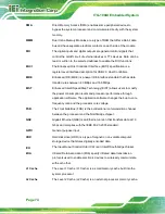
AC ’97 

Audio Codec 97 (AC’97) refers to a codec standard developed by Intel® 
in 1997. 

ACPI 

Advanced Configuration and Power Interface (ACPI) is an OS-directed 
configuration, power management, and thermal management interface. 

AHCI 

Advanced Host Controller Interface (AHCI) is a SATA Host controller 
register-level interface. 

ATA 

The Advanced Technology Attachment (ATA) interface connects storage 
devices including hard disks and CD-ROM drives to a computer. 

ARMD 

An ATAPI Removable Media Device (ARMD) is any ATAPI device that 
supports removable media, besides CD and DVD drives. 

ASKIR 

Amplitude Shift Keyed Infrared (ASKIR) is a form of modulation that 
represents a digital signal by varying the amplitude (“volume”) of the 
signal. A low amplitude signal represents a binary 0, while a high 
amplitude signal represents a binary 1. 

BIOS 

The Basic Input/Output System (BIOS) is firmware that is first run when 
the computer is turned on and can be configured by the end user 

CODEC 

The Compressor-Decompressor (CODEC) encodes and decodes digital 
audio data on the system.   

CompactFlash® 

CompactFlash® is a solid-state storage device. CompactFlash® devices 
use flash memory in a standard size enclosure. Type II is thicker than 
Type I, but a Type II slot can support both types. 

CMOS 

Complimentary metal-oxide-conductor is an integrated circuit used in 
chips like static RAM and microprocessors. 

COM 

COM refers to serial ports. Serial ports offer serial communication to 
expansion devices. The serial port on a personal computer is usually a 
male D-sub 9 connector. 

DAC 

The Digital-to-Analog Converter (DAC) converts digital signals to analog 
signals. 

DDR 

Double Data Rate refers to a data bus transferring data on both the rising 
and falling edges of the clock signal. 

Содержание ITG-100AI

Страница 1: ...ITG 100AI Embedded System Page i User Manual MODEL ITG 100AI Fanless Embedded System with Intel Atom x5 E3930 VGA GbE Two RS 232 422 485 Two USB 3 0 and RoHS Compliant Rev 1 00 October 2 2019 ...

Страница 2: ...ITG 100AI Embedded System Page ii Revision Date Version Changes October 2 2019 1 00 Initial release ...

Страница 3: ...ges arising out of the use or inability to use the product or documentation even if advised of the possibility of such damages This document contains proprietary information protected by copyright All rights are reserved No part of this manual may be reproduced by any mechanical electronic or other means in any form without prior written permission of the manufacturer TRADEMARKS All registered tra...

Страница 4: ...TION Cautionary messages should be heeded to help reduce the chance of losing data or damaging the product NOTE These messages inform the reader of essential but non critical information These messages should be read carefully as any directions or instructions contained therein can help avoid making mistakes HOT SURFACE This symbol indicates a hot surface that should not be touched without taking ...

Страница 5: ... PRECAUTIONS 11 3 3 BOTTOM COVER REMOVAL AND RE INSTALLATION 12 3 4 SO DIMM INSTALLATION 13 3 5 WIRELESS LAN MODULE INSTALLATION OPTIONAL 15 3 6 RS 232 422 485 SERIAL PORT CONNECTION 17 3 6 1 DB 9 RS 232 422 485 Serial Port Connection 17 3 6 2 RJ 45 RS 232 422 485 Serial Port Connection 18 3 7 AT ATX MODE SELECTION 21 3 7 1 AT Power Mode 21 3 7 2 ATX Power Mode 22 3 8 MOUNTING THE SYSTEM 22 3 9 PO...

Страница 6: ...ction 36 4 3 5 1 Console Redirection Settings 36 4 3 6 CPU Configuration 39 4 3 7 USB Configuration 40 4 3 8 iEi Feature 41 4 3 9 SATA Configuration 42 4 4 CHIPSET 43 4 4 1 North Bridge Configuration 44 4 4 1 1 Intel IGD Configuration 44 4 4 2 Southbridge Configuration 46 4 4 2 1 PCI Express Configuration 47 4 4 2 2 SCC Configuration 48 4 5 SECURITY 49 4 6 BOOT 50 4 7 EXIT 52 5 SOFTWARE INSTALLATI...

Страница 7: ...ty Precautions 64 B 1 2 Anti static Precautions 65 B 1 3 Product Disposal 66 B 2 MAINTENANCE AND CLEANING PRECAUTIONS 67 B 2 1 Maintenance and Cleaning 67 B 2 2 Cleaning Tools 67 C BIOS MENU OPTIONS 69 D TERMINOLOGY 72 E HAZARDOUS MATERIALS DISCLOSURE 76 ...

Страница 8: ...d Slot Location 16 Figure 3 7 Inserting the WLAN Card into the Slot at an Angle 16 Figure 3 8 Securing the WLAN Card 17 Figure 3 9 Serial Device Connector 18 Figure 3 10 DB 9 RS 232 422 485 Serial Port Connector 18 Figure 3 11 Serial Device Connector 19 Figure 3 12 RJ 45 RS 232 422 485 Serial Port Connector 19 Figure 3 13 DB 9 RS 232 422 485 Connector Pinout Location 20 Figure 3 14 AT ATX Switch L...

Страница 9: ...ge ix List of Tables Table 1 1 Technical Specifications 4 Table 2 1 Package List Contents 9 Table 3 1 RJ 45 RS 232 422 485 Serial Port Pinouts 19 Table 3 2 DB 9 RS 232 422 485 Connector Pinouts 20 Table 4 1 BIOS Navigation Keys 27 ...

Страница 10: ...ole Redirection 36 BIOS Menu 9 Console Redirection Settings 37 BIOS Menu 10 CPU Configuration 39 BIOS Menu 11 USB Configuration 40 BIOS Menu 12 iEi Feature 41 BIOS Menu 13 IDE Configuration 42 BIOS Menu 14 Chipset 43 BIOS Menu 15 Northbridge Chipset Configuration 44 BIOS Menu 16 Integrated Graphics 45 BIOS Menu 17 Southbridge Chipset Configuration 46 BIOS Menu 18 PCI Express Configuration 47 BIOS ...

Страница 11: ...ITG 100AI Embedded System Page 1 Chapter 1 1 Introduction ...

Страница 12: ...module pre installed with 8 GB memory Two RS 232 422 485 serial ports and two USB 3 1 GEN 1 ports ensure simplified connectivity to a variety of external peripheral devices 1 2 Features The ITG 100AI features are listed below Intel Atom x5 E3930 1 3GHz up to 1 8 GHz Two GbE LAN ports Two RS 232 422 485 M 2 A key slot for expansion Pre installed Mustang MPCIE MX2 2 x Intel Myriad X VPU for AI deep ...

Страница 13: ...dual core TDP 6 5W Chipset SoC System Memory 1x 204 pin DDR3L SO DIMM slot pre installed with 8 GB memory Storage SATADOM Pre installed 128GB eMMC 1 x eMMC 5 0 support up to 32GB optional Micro SD 1 x Micro SD Slot I O Interfaces USB 3 1 Gen 1 5Gb s 2 x USB 3 1 GEN 1 ports Ethernet 2 x RJ 45 PCIe GbE by I211 AT controller COM Port 2 x RS 232 422 485 DB 9 RJ45 Display 1 x VGA Resolution Up to 1920x...

Страница 14: ...70 C with air flow 10 90 non condensing Operating Shock Half sine wave shock 5G 11ms 100 shocks per axis IEC68 2 27 Operating Vibration MIL STD 810G 514 6C 1 Safety EMC CE FCC Watchdog Timer Programmable 1 255 sec min OS Supported OS Win10 Linux Ubuntu 16 04 LTS Table 1 1 Technical Specifications 1 4 Side Panel The side panel of the ITG 100AI has the following features Figure 1 2 1 x 9 36V DC IN 1...

Страница 15: ... the ITG 100AI has the following features Figure 1 3 1 x AT ATX Switch 1 x HDD LED 1 x Power button 1 x Power LED 1 x Reset button 2 x RJ 45 LAN connectors 2 x RS 232 422 485 serial port connectors DB 9 RJ45 2 x USB 3 1 GEN 1 connectors Figure 1 3 ITG 100AI Front Panel ...

Страница 16: ...ITG 100AI Embedded System Page 6 1 6 Physical Dimensions The physical dimensions of the ITG 100AI are shown below Figure 1 4 Physical Dimensions mm ...

Страница 17: ...ITG 100AI Embedded System Page 7 Chapter 2 2 Unpacking ...

Страница 18: ...out of the boxes Step 5 Remove both polystyrene ends one from each side Step 6 Make sure all the components listed in the packing list are present 2 2 Packing List NOTE If some of the components listed in the checklist below are missing please do not proceed with the installation Contact the IEI reseller or vendor you purchased the ITG 100AI from or contact an IEI sales representative directly To ...

Страница 19: ...Quantity Item and Part Number Image 1 Adapter P N 63040 010036 210 RS 1 Power cord 1 Power cable P N 32102 045700 100 RS 1 1 x RJ 45 to DB 9 COM port cable 1 Mounting Bracket 3 Screws M3 6 for DIN mount Table 2 1 Package List Contents ...

Страница 20: ...ITG 100AI Embedded System Page 10 Chapter 3 3 Installation ...

Страница 21: ...he board Self grounding Before handling the board touch any grounded conducting material During the time the board is handled frequently touch any conducting materials that are connected to the ground Use an anti static pad When configuring the ITG 100AI place it on an anti static pad This reduces the possibility of ESD damaging the ITG 100AI 3 2 Installation Precautions During installation be awa...

Страница 22: ...least 5 cm of clearance around the ITG 100AI to prevent overheating Grounding The ITG 100AI should be properly grounded The voltage feeds must not be overloaded Adjust the cabling and provide external overcharge protection per the electrical values indicated on the label attached to the back of the ITG 100AI 3 3 Bottom Cover Removal and Re installation Before installing or maintaining the internal...

Страница 23: ...s previously remove to secure the bottom cover 3 4 SO DIMM Installation WARNING Using incorrectly specified SO DIMM may cause permanently damage the ITG 100AI Please make sure the purchased SO DIMM complies with the memory specifications of the ITG 100AI To install a SO DIMM into a SO DIMM socket please follow the steps below Step 1 Remove the bottom cover from the ITG 100AI Please follow the inst...

Страница 24: ...bridge in the socket Figure 3 4 Step 4 Push the SO DIMM into the socket at an angle Figure 3 4 Figure 3 4 SO DIMM Installation Step 5 Gently pull the arms of the SO DIMM socket out and push the rear of the SO DIMM down Figure 3 4 Step 6 Release the arms on the SO DIMM socket They clip into place and secure the SO DIMM in the socket Step 7 Install the bracket that was previously removed in the same...

Страница 25: ...d installation The M 2 card slot is located under the accelerator card To install the optional wireless LAN WLAN module please follow the steps below Step 1 Remove the bottom cover from the ITG 100AI Please follow the instruction described in Section 3 3 Step 2 Remove the accelerator card by removing the two retention screws as shown below Figure 3 5 Accelerator Card Retention Screws Step 3 Locate...

Страница 26: ...ion Step 4 Line up the notch on the module with the notch on the slot Slide the WLAN card into the socket at an angle of about 20º Figure 3 7 Figure 3 7 Inserting the WLAN Card into the Slot at an Angle Step 5 Secure the WLAN card with an M2 3 retention screw Figure 3 8 ...

Страница 27: ...he other is RJ 45 connector 3 6 1 DB 9 RS 232 422 485 Serial Port Connection DB 9 RS 232 422 485 serial port devices can be attached to the DB 9 port on the bottom panel Step 1 Locate the DB 9 connector The locations of the DB 9 connector are shown in Figure 1 3 Step 2 Insert the serial connector Insert the DB 9 connector of a serial device into the DB 9 connector on the external peripheral interf...

Страница 28: ...S 232 422 485 Serial Port Connection The RJ 45 RS 232 422 485 serial port connects to a cable with a standard DB 9 connector at the other end cables included Follow the steps below to connect a serial device to the ITG 100AI Step 1 Locate the RJ 45 connector The location of the RJ 45 serial port connector is shown in Chapter 2 The RJ 45 connectors for the serial ports can be identified easily as t...

Страница 29: ...igure 3 11 Serial Device Connector Step 4 Secure the connector Secure the serial device connector to the external interface by tightening the two retention screws on either side of the connector Figure 3 12 RJ 45 RS 232 422 485 Serial Port Connector Pin RS 232 RS 422 RS 485 1 NDCD1 TX DATA 2 NDSR1 3 NRX1 TX DATA 4 NRTS1 5 NTX1 RX 6 NCTS1 7 NDTR1 RX 8 NRI1 Table 3 1 RJ 45 RS 232 422 485 Serial Port...

Страница 30: ... 6 NDSR 7 NRTS 8 NCTS 9 NRI Table 3 2 DB 9 RS 232 422 485 Connector Pinouts NOTE The communication protocol of the serial ports is set through the BIOS menu in Advanced F81866 Super IO Configuration Serial Port 1 2 Configuration Use the Device Mode BIOS option to configure the correspondent serial ports refer to Sections 4 3 2 1 1 and 4 3 2 1 2 for detailed information ...

Страница 31: ...Figure 3 14 AT ATX Switch Location Step 2 Adjust the AT ATX switch Step 0 3 7 1 AT Power Mode With the AT mode selected the power is controlled by a central power unit rather than a power switch The ITG 100AI panel PC turns on automatically when the power is connected The AT mode benefits a production line to control multiple panel PCs from a central management center and other applications includ...

Страница 32: ...t individually and controlled remotely Other possible application includes Security surveillance Point of Sale POS Advertising terminal 3 8 Mounting the System To mount the ITG 100AI embedded system onto a DIN rail please follow the steps below Step 1 Attach the DIN mount bracket to the rear panel of the ITG 100AI Secure the bracket to the ITG 100AI with three supplied retention screws Figure 3 15...

Страница 33: ...3 Figure 3 15 Mounting the DIN Rail Step 2 Place the DIN rail against the back of the DIN mount bracket making sure the edges of the DIN rail are between the clamps of the DIN mount bracket Figure 3 16 Figure 3 16 Mounting to DIN Rail ...

Страница 34: ...ess the power button for 6 seconds Figure 3 17 Power Button Location 3 10 Reset the System The reset button enables user to reboot the system when the system is turned on To reboot the system follow the steps below Step 3 Locate the reset button on the front panel Figure 3 18 Figure 3 18 Reset Button Location Step 4 Press the reset button Step 0 ...

Страница 35: ...ITG 100AI Embedded System Page 25 Chapter 4 4 BIOS ...

Страница 36: ...Press the DELETE or F2 key as soon as the system is turned on or 2 Press the DELETE or F2 key when the Press Del to enter SETUP message appears on the screen 0 If the message disappears before the DELETE or F2 key is pressed restart the computer and try again 4 1 2 Using Setup Use the arrow keys to highlight items press ENTER to select use the PageUp and PageDown keys to change entries press F1 fo...

Страница 37: ...w describing the appropriate keys to use and the possible selections for the highlighted item appears To exit the Help Window press ESC or the F1 key again 4 1 4 Unable to Reboot after Configuration Changes If the computer cannot boot after changes to the system configuration is made CMOS defaults Use the jumper described in Chapter 3 4 1 5 BIOS Menu Bar The menu bar on top of the BIOS screen has ...

Страница 38: ... 08 16 2019 08 36 12 iWDD Vendor iEi iWDD Version SAL3ER01 bin Platform firmware Information BXT SOC F1 MRC Version 0 56 PUNIT FW 1A PMC FW 03 20 TXE FW 3 1 65 2288 GOP 0 0 0036 CPU Flavor BXT Notebook Desktop 1 Board ID Oxbow Hill CRB 06 Fab ID FAB A Memory Information Total Memory 8192 MB Memory Speed 1866 MHz System Date Fri 08 23 2019 System Time 15 43 27 Access Level Administrator Set the Dat...

Страница 39: ...the sections below may cause the system to malfunction Make sure that the settings made are compatible with the hardware Aptio Setup Utility Copyright C 2018 American Megatrends Inc Main Advanced Chipset Security Boot Save Exit ACPI Settings F81866 Super IO Configuration Hardware Monitor RTC Wake Settings Serial Port Console Redirection CPU Configuration USB Configuration iEi Feature SATA Configur...

Страница 40: ...t Screen Select Item EnterSelect Change Opt F1 General Help F2 Previous Values F3 Optimized Defaults F4 Save Exit ESC Exit Version 2 18 1263 Copyright C 2018 American Megatrends Inc BIOS Menu 3 ACPI Configuration ACPI Sleep State S3 only Suspend to RAM The fields in ACPI Sleep State option cannot be changed S3 Suspend to RAM DEFAULT The caches are flushed and the CPU is powered off Power to the RA...

Страница 41: ...neral Help F2 Previous Values F3 Optimized Defaults F4 Save ESC Exit Version 2 18 1263 Copyright C 2018 American Megatrends Inc BIOS Menu 4 Super IO Configuration 4 3 2 1 Serial Port n Configuration Use the Serial Port n Configuration menu BIOS Menu 5 to configure the serial port n Aptio Setup Utility Copyright C 2018 American Megatrends Inc Advanced Serial Port 1 Configuration Serial Port Enabled...

Страница 42: ... Enables serial port RS 232 support RS422 Enables serial port RS 422 support RS485 Enables serial port RS 485 support 4 3 2 1 2 Serial Port 2 Configuration Serial Port Enabled Use the Serial Port option to enable or disable the serial port Disabled Disable the serial port Enabled DEFAULT Enable the serial port Device Mode RS232 Use the Device Mode option to select the serial port mode RS232 DEFAUL...

Страница 43: ...led DEFAULT Enable the serial port 4 3 2 1 4 Serial Port 4 Configuration Serial Port Enabled Use the Serial Port option to enable or disable the serial port Disabled Disable the serial port Enabled DEFAULT Enable the serial port 4 3 3 Hardware Monitor The Hardware Monitor menu BIOS Menu 6 contains the fan configuration submenus and displays operating temperature fan speeds and system voltages ...

Страница 44: ...Opt F1 General Help F2 Previous Values F3 Optimized Defaults F4 Save Exit ESC Exit Version 2 18 1263 Copyright C 2018 American Megatrends Inc BIOS Menu 6 Hardware Monitor PC Health Status The following system parameters and values are shown The system parameters that are monitored are Temperatures o CPU Temperature o System temperature Voltages o VSCC_SVID o V5_S o V12_S o V3P3_S 4 3 4 RTC Wake Se...

Страница 45: ...rican Megatrends Inc BIOS Menu 7 RTC Wake Settings Wake system with Fixed Time Disabled Use the Wake system with Fixed Time option to enable or disable the system wake on alarm event Disabled DEFAULT The real time clock RTC cannot generate a wake event Enabled If selected the Wake up every day option appears allowing you to enable to disable the system to wake every day at the specified time Besid...

Страница 46: ...ection Settings COM4 Console Redirection Disabled Console Redirection Settings Console Redirection Enable or Disable Select Screen Select Item EnterSelect F1 General Help F2 Previous Values F3 Optimized Defaults F4 Save ESC Exit Version 2 18 1263 Copyright C 2018 American Megatrends Inc BIOS Menu 8 Serial Port Console Redirection Console Redirection Disabled Use Console Redirection option to enabl...

Страница 47: ...Optimized Defaults F4 Save ESC Exit Version 2 18 1263 Copyright C 2018 American Megatrends Inc BIOS Menu 9 Console Redirection Settings Terminal Type ANSI Use the Terminal Type option to specify the remote terminal type VT100 The target terminal type is VT100 VT100 The target terminal type is VT100 VT UTF8 The target terminal type is VT UTF8 ANSI DEFAULT The target terminal type is ANSI Bits per s...

Страница 48: ...cting the transmission errors None DEFAULT No parity bit is sent with the data bits Even The parity bit is 0 if the number of ones in the data bits is even Odd The parity bit is 0 if the number of ones in the data bits is odd Mark The parity bit is always 1 This option does not provide error detection Space The parity bit is always 0 This option does not provide error detection Stop Bits 1 Use the...

Страница 49: ...lization Technology Disabled EIST Enabled C States Disabled When enabled a VMM can utilize the additional hardware capabilities provided by Vanderpool Technology Select Screen Select Item EnterSelect F1 General Help F2 Previous Values F3 Optimized Defaults F4 Save ESC Exit Version 2 18 1263 Copyright C 2018 American Megatrends Inc BIOS Menu 10 CPU Configuration Intel Virtualization Technology Disa...

Страница 50: ...e USB settings Aptio Setup Utility Copyright C 2018 American Megatrends Inc Advanced USB Configuration USB Devices 1 Keyboard Legacy USB Support Enabled Enables Legacy USB support AUTO option disables legacy support if no USB devices are connected DISABLE option will keep USB devices available only for EFI applications Select Screen Select Item EnterSelect F1 General Help F2 Previous Values F3 Opt...

Страница 51: ...isabled Legacy USB support disabled 4 3 8 iEi Feature Use the iEi Feature menu BIOS Menu 12 to configure the iEi features Aptio Setup Utility Copyright C 2018 American Megatrends Inc Advanced iEi Feature Auto Recovery Function Disabled Auto Recovery Function Reboot and recover system automatically within 10 min when OS crashes Please install Auto Recovery API service before enabling this function ...

Страница 52: ...t Plug Disabled mSATA Port Not Present Hot Plug Disabled Determines how SATA controller s operate Select Screen Select Item EnterSelect F1 General Help F2 Previous Values F3 Optimized Defaults F4 Save ESC Exit Version 2 18 1263 Copyright C 2018 American Megatrends Inc BIOS Menu 13 IDE Configuration SATA Mode Selection AHCI Use the SATA Mode Selection option to configure SATA devices as normal IDE ...

Страница 53: ...hipset BIOS menu may cause the system to malfunction Aptio Setup Utility Copyright C 2018 American Megatrends Inc Main Advanced Chipset Security Boot Save Exit North Bridge South Bridge North Bridge Parameters Select Screen Select Item EnterSelect Change Opt F1 General Help F2 Previous Values F3 Optimized Defaults F4 Save Exit ESC Exit Version 2 18 1263 Copyright C 2018 American Megatrends Inc BIO...

Страница 54: ...l IGD Configuration Select Screen Select Item EnterSelect Change Opt F1 General Help F2 Previous Values F3 Optimized Defaults F4 Save Exit ESC Exit Version 2 18 1263 Copyright C 2018 American Megatrends Inc BIOS Menu 15 Northbridge Chipset Configuration Memory Information The Memory Information lists a brief summary of the on board memory The fields in Memory Information cannot be changed 4 4 1 1 ...

Страница 55: ...263 Copyright C 2018 American Megatrends Inc BIOS Menu 16 Integrated Graphics Primary Display IGD Use the Primary Display option to select the primary graphics controller the system uses The following options are available IGD Default PCIe DVMT Pre Allocated 256MB Use the DVMT Pre Allocated option to set the amount of system memory allocated to the integrated graphics processor when the system boo...

Страница 56: ...ed OS Selection Windows PCI Express Configuration SCC Configuration Select the state system should be when restoring on AC Power Loss Select Screen Select Item EnterSelect Change Opt F1 General Help F2 Previous Values F3 Optimized Defaults F4 Save Exit ESC Exit Version 2 18 1263 Copyright C 2018 American Megatrends Inc BIOS Menu 17 Southbridge Chipset Configuration Restore AC Power Loss Last State...

Страница 57: ...LT Android 4 4 2 1 PCI Express Configuration Use the PCI Express Configuration menu BIOS Menu 18 to select the support type of the PCIe Mini slot Aptio Setup Utility Copyright C 2018 American Megatrends Inc Chipset PCI Express Configuration Compliance Mode Disabled M 2 mPCIE Compliance Mode Enable Disable Select Screen Select Item Enter Select Change Opt F1 General Help F2 Previous Values F3 Optim...

Страница 58: ...configure the SCC settings Aptio Setup Utility Copyright C 2018 American Megatrends Inc Chipset SCC SD Card Support D27 F0 Enabled SCC eMMC Support D28 F0 Enabled eMMC Max Speed HS400 Enable Disable SCC SD Card Support Select Screen Select Item Enter Select Change Opt F1 General Help F2 Previous Values F3 Optimized Defaults F4 Save Exit ESC Exit Version 2 18 1263 Copyright C 2018 American Megatren...

Страница 59: ...ght C 2018 American Megatrends Inc Main Advanced Chipset Security Boot Save Exit Password Description If ONLY the Administrator s password is set then this only limits access to Setup and is only asked for when entering Setup If ONLY the User s password is set then this is a power on password and must be entered to boot or enter Setup In Setup the User will have Administrator rights The password l...

Страница 60: ...Boot Option Priorities Boot Option 1 P0 SATADOM SH SME 4 Hard Drive BBS Priorities Select the keyboard NumLock state Select Screen Select Item EnterSelect F1 General Help F2 Previous Values F3 Optimized Defaults F4 Save ESC Exit Version 2 18 1263 Copyright C 2018 American Megatrends Inc BIOS Menu 21 Boot Bootup NumLock State On Use the Bootup NumLock State BIOS option to specify if the number lock...

Страница 61: ... POST messages displayed Enabled DEFAULT OEM Logo displayed instead of POST messages Launch PXE OpROM Disabled Use the Launch PXE OpROM option to enable or disable boot option for legacy network devices Disabled DEFAULT Ignore all PXE Option ROMs Enabled Load PXE Option ROMs Option ROM Messages Force BIOS Use the Option ROM Messages option to set the Option ROM display mode Force BIOS DEFAULT Sets...

Страница 62: ...ices in this group 4 7 Exit Use the Exit menu BIOS Menu 22 to load default BIOS values optimal failsafe values and to save configuration changes Aptio Setup Utility Copyright C 2018 American Megatrends Inc Main Advanced Chipset Security Boot Save Exit Save Changes and Reset Discard Changes and Reset Restore Defaults Save as User Defaults Restore User Defaults Reset the system after saving the chan...

Страница 63: ... system without saving the changes made to the BIOS configuration setup program Restore Defaults Use the Restore Defaults option to load the optimal default values for each of the parameters on the Setup menus F3 key can be used for this operation Save as User Defaults Use the Save as User Defaults option to save the changes done so far as user defaults Restore User Defaults Use the Restore User D...

Страница 64: ...ITG 100AI Embedded System Page 54 Chapter 5 5 Software Installation ...

Страница 65: ... to find all the relevant software utilities and documentation Figure 5 1 IEI Resource Download Center 5 1 1 Driver Download To download drivers from IEI Resource Download Center follow the steps below Step 1 Go to https download ieiworld com Type ITG 100AI and press Enter Step 2 All product related software utilities and documentation will be listed You can choose Driver to filter the result ...

Страница 66: ... or click the small arrow to find an individual driver and click the file name to download NOTE To install software from the downloaded ISO image file in Windows 8 8 1 or 10 double click the ISO file to mount it as a virtual drive to view its content On Windows 7 system an additional tool such as Virtual CD ROM Control Panel from Microsoft is needed to mount the file ...

Страница 67: ...nVINO Toolkit via website follow the steps below Step 1 Go to https software intel com en us openvino toolkit Step 2 Click Get Started then choose your configuration from Development Environment Installation Guides Step 3 Follow the instruction to complete the installation procedure ...

Страница 68: ...ITG 100AI Embedded System Page 58 Appendix A A Regulatory Compliance ...

Страница 69: ...s in compliance with the essential requirements and other relevant provisions of Directive 2014 53 EU Български Bulgarian IEI Integration Corp декларира че този оборудване е в съответствие със съществените изисквания и другите приложими правила на Директива 2014 53 EU Česky Czech IEI Integration Corp tímto prohlašuje že tento zařízení je ve shodě se základními požadavky a dalšími příslušnými ustan...

Страница 70: ... autres dispositions pertinentes de la directive 2014 53 EU Italiano Italian IEI Integration Corp dichiara che questo apparecchio è conforme ai requisiti essenziali ed alle altre disposizioni pertinenti stabilite dalla direttiva 2014 53 EU Latviski Latvian IEI Integration Corp deklarē ka iekārta atbilst būtiskajām prasībām un citiem ar to saistītajiem noteikumiem Direktīvas 2014 53 EU Lietuvių Lit...

Страница 71: ...nt este in conformitate cu cerinţele esenţiale şi cu celelalte prevederi relevante ale Directivei 2014 53 EU Slovensko Slovenian IEI Integration Corp izjavlja da je ta opreme v skladu z bistvenimi zahtevami in ostalimi relevantnimi določili direktive 2014 53 EU Slovensky Slovak IEI Integration Corp týmto vyhlasuje že zariadenia spĺňa základné požiadavky a všetky príslušné ustanovenia Smernice 2014...

Страница 72: ...terference at his own expense Federal Communication Commission Interference Statement This equipment has been assembled with components that comply with the limits for a Class B digital device pursuant to Part 15 of the FCC Rules These limits are designed to provide reasonable protection against harmful interference in a residential installation This equipment generates uses and can radiate radio ...

Страница 73: ...ITG 100AI Embedded System Page 63 B Safety Precautions Appendix B ...

Страница 74: ...event the risk of electric shock make sure power cord is unplugged from wall socket To fully disengage the power to the unit please disconnect the power cord from the AC outlet Refer servicing to qualified service personnel The AC outlet shall be readily available and accessible Do not apply voltage levels that exceed the specified voltage range Doing so may cause fire and or an electrical shock U...

Страница 75: ...including the ITG 100AI Dry climates are especially susceptible to ESD It is therefore critical that whenever the ITG 100AI is opened and any of the electrical components are handled the following anti static precautions are strictly adhered to Wear an anti static wristband Wearing a simple anti static wristband can help to prevent ESD from damaging any electrical component Self grounding Before h...

Страница 76: ...e is classified as electronic device in terms of the European Directive 2012 19 EU WEEE and must not be disposed of as domestic garbage EU wide legislation as implemented in each Member State requires that waste electrical and electronic products carrying the mark left must be disposed of separately from normal household waste This includes monitors and electrical accessories such as signal cables...

Страница 77: ...e it with a piece of soft dry cloth or a slightly moistened cloth The interior of the device does not require cleaning Keep fluids away from the device interior Be cautious of all small removable components when vacuuming the device Never drop any objects or liquids through the openings of the device Be cautious of any possible allergic reactions to solvents or chemicals used when cleaning the dev...

Страница 78: ...sing a vacuum specifically designed for computers is one of the best methods of cleaning the device Dust and dirt can restrict the airflow in the device and cause its circuitry to corrode Cotton swabs Cotton swaps moistened with rubbing alcohol or water are excellent tools for wiping hard to reach areas Foam swabs Whenever possible it is best to use lint free swabs such as foam swabs for cleaning ...

Страница 79: ...ITG 100AI Embedded System Page 69 Appendix C C BIOS Menu Options ...

Страница 80: ...e Disabled 35 Console Redirection Disabled 36 Terminal Type ANSI 37 Bits per second 115200 37 Data Bits 8 38 Parity None 38 Stop Bits 1 38 Intel Virtualization Technology Disabled 39 EIST Enabled 39 C States Disabled 40 USB Devices 40 Legacy USB Support Enabled 41 Auto Recovery Function Disabled 41 SATA Mode Selection AHCI 42 Hot Plug Disabled 42 Memory Information 44 Primary Display IGD 45 DVMT P...

Страница 81: ...rator Password 50 User Password 50 Bootup NumLock State On 50 Quiet Boot Enabled 51 Launch PXE OpROM Disabled 51 Option ROM Messages Force BIOS 51 UEFI Boot Disabled 51 Boot Option Priority 52 Hard Drive BBS Priorities 52 Save Changes and Reset 53 Discard Changes and Reset 53 Restore Defaults 53 Save as User Defaults 53 Restore User Defaults 53 ...

Страница 82: ...ITG 100AI Embedded System Page 72 Appendix D D Terminology ...

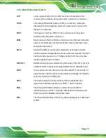
Страница 83: ... a binary 0 while a high amplitude signal represents a binary 1 BIOS The Basic Input Output System BIOS is firmware that is first run when the computer is turned on and can be configured by the end user CODEC The Compressor Decompressor CODEC encodes and decodes digital audio data on the system CompactFlash CompactFlash is a solid state storage device CompactFlash devices use flash memory in a sta...

Страница 84: ...eedStep Technology EIST allows users to modify the power consumption levels and processor performance through application software The application software changes the bus to core frequency ratio and the processor core voltage FSB The Front Side Bus FSB is the bi directional communication channel between the processor and the Northbridge chipset GbE Gigabit Ethernet GbE is an Ethernet version that...

Страница 85: ... transfers between storage devices and the computer chipsets The SATA bus has transfer speeds up to 1 5 Gbps and the SATA II bus has data transfer speeds of up to 3 0 Gbps S M A R T Self Monitoring Analysis and Reporting Technology S M A R T refers to automatic status checking technology implemented on hard disk drives UART Universal Asynchronous Receiver transmitter UART is responsible for asynch...

Страница 86: ...ITG 100AI Embedded System Page 76 Appendix E E Hazardous Materials Disclosure ...

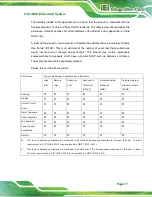
Страница 87: ...lamps These components will be separately marked Please refer to the following table Part Name Toxic or Hazardous Substances and Elements Lead Pb Mercury Hg Cadmium Cd Hexavalent Chromium CR VI Polybrominated Biphenyls PBB Polybrominated Diphenyl Ethers PBDE Housing O O O O O O Display O O O O O O Printed Circuit Board O O O O O O Metal Fasteners O O O O O O Cable Assembly O O O O O O Fan Assembly...

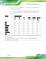
Страница 88: ...是电池或灯管 这些元 件将会单独标示出来 部件名称 有毒有害物质或元素 铅 Pb 汞 Hg 镉 Cd 六价铬 CR VI 多溴联苯 PBB 多溴二苯 醚 PBDE 壳体 O O O O O O 显示 O O O O O O 印刷电路板 O O O O O O 金属螺帽 O O O O O O 电缆组装 O O O O O O 风扇组装 O O O O O O 电力供应组装 O O O O O O 电池 O O O O O O O 表示该有毒有害物质在该部件所有物质材料中的含量均在 SJ T 11363 2006 现由 GB T 26572 2011 取代 标准规定的限量要求以下 X 表示该有毒有害物质至少在该部件的某一均质材料中的含量超出 SJ T 11363 2006 现由 GB T 26572 2011 取代 标准规定的限量要求 ...

Отзывы: