background image


iSignager-1000-Q354 Digital Signage Player

Page 92 

Step 9: 

Click 

N

EXT

 to continue. 

Step 10: 

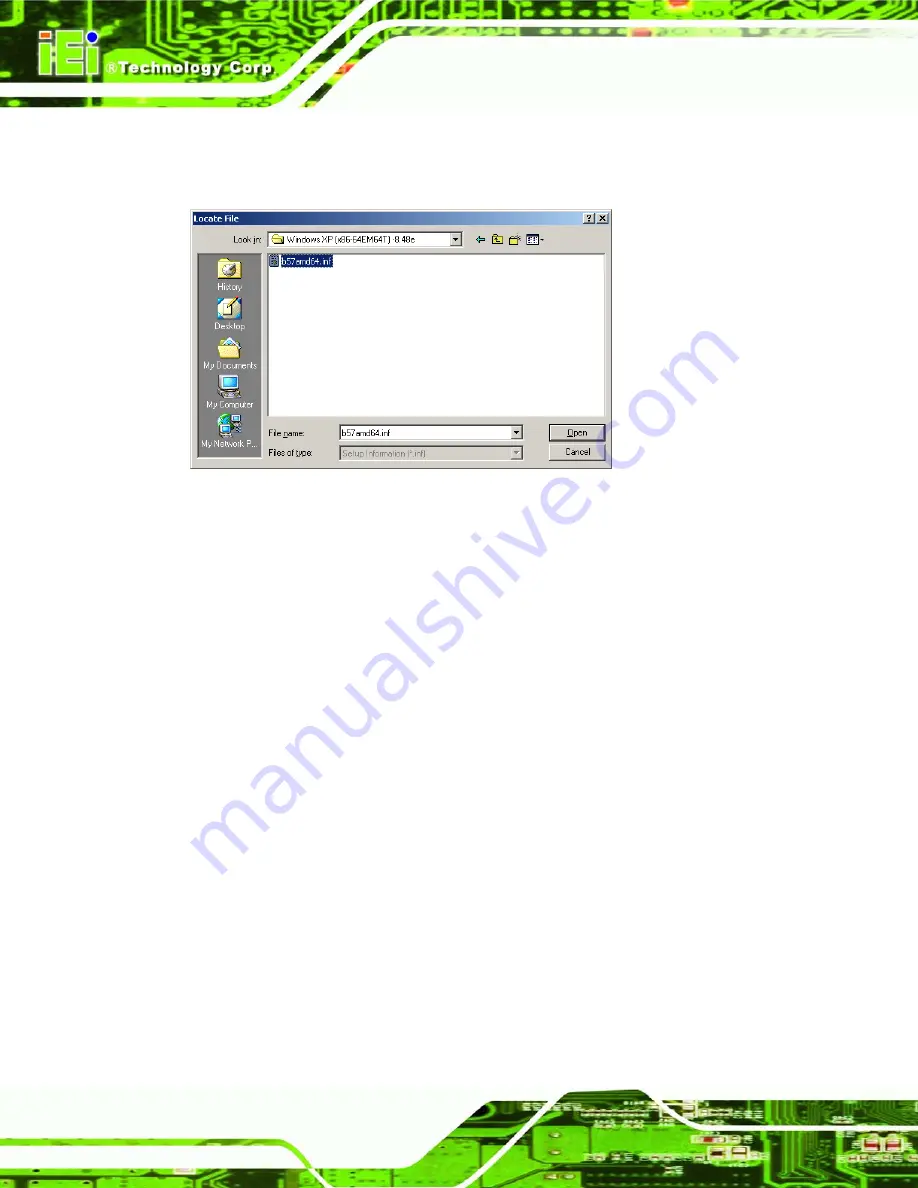
The Locate File window appears (

Figure 6-25

). 

Figure 6-25: Location Browsing Window 

Step 11: 

Select the 

PRO2KXP.exe

 file under the “

X:\3-LAN

” directory in the 

Locate File


window, where “

X:\”

 is the system CD drive. 

Step 12: 

Click 

O

PEN 

and the driver is installed.

Step 0:


6.7 Atheros Wireless LAN Driver Installation 

To install the Atheros wireless LAN driver, please follow the steps below. 

Step 1: 

Select the WLAN driver from the list in 

Figure 6-1

 and locate the 

X:\WLAN\ 

AW-GE780_D5.3.0.45_WHQL\Install_CD\

 directory. 

Step 2: 

Double click the 

setup.exe

 icon. 

Step 3: 

The Atheros Client Installation Program screen appears. See 

Figure 6-26

.  

Содержание iSignager-1000-Q354

Страница 1: ...Technology Corp User Manual iSignager 1000 Q354 Digital Signage Player MODEL iSignager 1000 Q354 Intel Core 2 Duo CPU Based Digital Signage Player with 320 GB HDD DVD Combo 2 0 GB DDR2 GbE LAN PoweredUSB 5V 12V RS 232 RoHS Compliant Rev 1 00 28 April 2009 ...

Страница 2: ...iSignager 1000 Q354 Digital Signage Player Page ii Revision Date Version Changes 28 April 2009 1 00 Initial release ...

Страница 3: ...tial damages arising out of the use or inability to use the product or documentation even if advised of the possibility of such damages This document contains proprietary information protected by copyright All rights are reserved No part of this manual may be reproduced by any mechanical electronic or other means in any form without prior written permission of the manufacturer TRADEMARKS All regis...

Страница 4: ...2 3 2 Rear Panel Overview 10 2 3 2 1 Rear Panel Connectors and Indicators 11 2 4 INTERNAL OVERVIEW 12 3 SYSTEM COMPONENTS 14 3 1 ISIGNAGER 1000 Q354 MOTHERBOARD 15 3 1 1 POS Motherboard Overview 15 3 1 2 CPU Support 16 3 1 3 Onboard Chipsets 17 3 1 3 1 Northbridge and Southbridge Chipsets 17 3 1 3 2 Intel Q35 Northbridge Chipset 17 3 1 3 3 ICH9DO Southbridge Chipset 18 3 1 4 Ethernet Controllers 1...

Страница 5: ...4 2 4 Foot Pad Installation 29 4 2 5 Cable Connections 29 4 3 POWER ON PROCEDURE 30 4 3 1 Installation Checklist 30 4 3 2 Power on Procedure 30 5 AMI BIOS 32 5 1 INTRODUCTION 33 5 1 1 Starting Setup 33 5 1 2 Using Setup 33 5 1 3 Getting Help 34 5 1 4 Unable to Reboot After Configuration Changes 34 5 1 5 BIOS Menu Bar 34 5 2 MAIN 35 5 3 ADVANCED 36 5 3 1 CPU Configuration 37 5 3 2 IDE Configuration...

Страница 6: ...onfiguration 74 5 8 EXIT 75 6 DRIVER INSTALLATION 77 6 1 AVAILABLE SOFTWARE DRIVERS 78 6 2 DRIVER CD 78 6 3 INTEL CHIPSET DRIVER INSTALLATION 79 6 4 REALTEK HD AUDIO DRIVER INSTALLATION 82 6 4 1 BIOS Setup 82 6 4 2 Driver Installation 82 6 5 INTEL GRAPHICS MEDIAACCELERATOR DRIVER INSTALLATION 85 6 6 LAN DRIVER FOR GBE LAN INSTALLATION 88 6 7 ATHEROS WIRELESS LAN DRIVER INSTALLATION 92 6 8 INTEL AC...

Страница 7: ... 8 TROUBLESHOOTING AND MAINTENANCE 120 8 1 ISIGNAGER 1000 Q354 SYSTEM MAINTENANCE OVERVIEW 121 8 2 SYSTEM TROUBLESHOOTING 121 8 2 1 The System Doesn t Turn On 121 8 2 2 The System Doesn t Boot Up 122 8 3 JUMPER SETTING AND EXPANSION CARD INSTALLATION 123 8 3 1 Cover Case Removal 123 8 3 2 Configure the Jumper Settings 124 8 3 3 Expansion Card Installation Optional 124 8 4 COMPONENT REPLACEMENT PRO...

Страница 8: ...2 Cleaning Tools 143 B INTERFACE CONNECTORS 145 B 1 PERIPHERAL INTERFACE CONNECTORS 146 C BIOS MENU OPTIONS 152 C 1 BIOS CONFIGURATION OPTIONS 153 D WATCHDOG TIMER 156 E HAZARDOUS MATERIALS DISCLOSURE 159 E 1 HAZARDOUS MATERIAL DISCLOSURE TABLE FOR IPB PRODUCTS CERTIFIED AS ROHS COMPLIANT UNDER 2002 95 EC WITHOUT MERCURY 160 F INTEL MATRIX STORAGE MANAGER 163 F 1 INTRODUCTION 164 F 1 1 Precautions...

Страница 9: ...ble Drivers 78 Figure 6 2 Chipset Driver Installation Program 79 Figure 6 3 Chipset Driver Installation Welcome Screen 80 Figure 6 4 Chipset Driver Installation License Agreement 80 Figure 6 5 Chipset Driver Readme File Information 81 Figure 6 6 Chipset Driver Installation Complete 81 Figure 6 7 The InstallShield Wizard Starts 82 Figure 6 8 Preparing Setup Screen 83 Figure 6 9 InstallShield Wizard...

Страница 10: ...On Feature Selection 96 Figure 6 33 Wireless LAN Driver Installation 96 Figure 6 34 Wireless LAN Driver Install Wizard Completed 97 Figure 6 35 Intel AMT Driver Directory 98 Figure 6 36 Intel AMT Driver Installation Icon 98 Figure 6 37 Intel AMT Welcome Screen 99 Figure 6 38 Intel AMT License Agreement 99 Figure 6 39 Intel AMT Readme File 100 Figure 6 40 Intel AMT Setup Operations 100 Figure 6 41 ...

Страница 11: ...over Retention Screw 124 Figure 8 4 Expansion Slot Cover Retention Screw Rear Panel 125 Figure 8 5 System Fan Bracket Retention Screws 126 Figure 8 6 System Fan Retention Screws 126 Figure 8 7 HDD Bracket Retention Screws 127 Figure 8 8 HDD Retention Screws 128 Figure 8 9 Rear Panel Connector Retention Screws 129 Figure 8 10 Motherboard Connectors 130 Figure 8 11 Motherboard Retention Screws 131 F...

Страница 12: ...pecifications 6 Table 3 1 Peripheral Interface Connectors 19 Table 3 2 Rear Panel Connectors 20 Table 3 3 Jumpers 21 Table 3 4 ATX Power Select Jumper Settings 21 Table 3 5 Clear CMOS Jumper Settings 23 Table 3 6 COM 1 2 Pin 9 Setting Jumper Settings 24 Table 3 7 COM 3 4 Pin 9 Setting Jumper Settings 25 Table 4 1 Package List Contents 28 Table 5 1 BIOS Navigation Keys 34 ...

Страница 13: ...nfiguration Advanced Power Configuration 51 Menu 10 Power Configuration 52 Menu 11 AHCI Configuration 54 Menu 12 AHCI Port n Configuration Menu 55 Menu 13 Intel AMT Configuration 56 Menu 14 ME Subsystem Configuration 57 Menu 15 Remote Access Configuration Advanced 59 Menu 16 USB Configuration 62 Menu 17 PCI PnP Configuration 64 Menu 18 Boot 66 Menu 19 Boot Settings Configuration 67 Menu 20 Securit...

Страница 14: ......

Страница 15: ...iSignager 1000 Q354 Digital Signage Player Page 1 1 Introduction Chapter 1 ...

Страница 16: ...twork connection The preinstalled 320 GB HDD and 2 GB DDR2 SDRAM make the iSignager 1000 Q354 a ready to use system The flexible PCI PCIe expansion allows the iSignager 1000 Q354 to meet multiple application requirements The iSignager 1000 Q354 is designed for ease of use and easy installation 1 1 1 iSignager 1000 Q354 Benefits The iSignager 1000 Q354 has the following benefits Easy installation a...

Страница 17: ...n the PCIe riser card 3 5 320 GB HDD and DVD combo drive preinstalled PCIe x1 and PCIe x16 expansion cards supported 1 2 Technical Specifications The specifications for the Intel based iSignager 1000 Q354 listed below iSignager 1000 Q354 CPU 3 0 GHz Intel Core 2 Duo E8400 with 6 MB L2 cache or 2 66 GHz Intel Core 2 Quad Q9400 with 6 MB L2 cache System Chipset Northbridge Intel Q35 Southbridge ICH9...

Страница 18: ... connector 1 x PS 2 Mouse connector ODD One DVD combo drive supports CD R CD RW DVD R HDD One preinstalled 3 5 320 GB HDD the system supports two 3 5 HDD drive bays SSD One CompactFlash Type II slot Expansion Slot One preinstalled PCIe riser card including 1 x PCIe mini slot preinstalled with a wireless LAN module 1 x PCIe x1 1 x PCIe x16 Power Supply 270 W ATX power supply preinstalled input volt...

Страница 19: ...ted in Table 1 2 Model ACE A627A Input Type 90 264 V AC full range 3 3 V 5 V 12 V 12 V 2 12 V 5 VSB Output Voltage 16 A 0 5 A min 18 A 0 5 A min 16 A 1 A min 10 A 1 A min 0 8 A 0 A min 2 5 A 0 A min Efficiency 80 Temperature Operating 0ºC 50ºC Storage 20ºC 80ºC MTBF 100 000 hrs Output Connector 1 x 20 pin ATX connector 1 x 4 pin 12 V CPU connector 3 x HDD power connector Dimensions 150 mm x 81 5 m...

Страница 20: ...ard IEEE 802 11 b g Interface PCIe mini card Connectors 2 x U FL R SMT Antenna connectors Frequency Band 2412 MHz 2472 MHz Modulation 802 11g OFDM 802 11b CCK 11 5 5 Mbps DQPSK 2 Mbps BPSK 1 Mbps Output Power 802 11b typical 16 1 5 dBm 802 11g typical 13 1 5 dBm Receive Sensitivity 802 11b typical 76 dBm at 11 Mbps 802 11g typical 68 dBm at 54 Mbps Operating Voltage 3 3 V Dimensions 30 00 mm x 51 ...

Страница 21: ...iSignager 1000 Q354 Digital Signage Player Page 7 2 Mechanical Description Chapter 2 ...

Страница 22: ...motherboard and the power module are installed inside the bottom of the chassis Featuring two GbE six USB four serial communication ports as well as audio VGA parallel port and cash drawer connectors the iSignager 1000 Q354 offers system integrators and developers the best selection of robust and high performance integrated service platforms A CompactFlash slot on the rear panel supports one Type ...

Страница 23: ...iSignager 1000 Q354 Digital Signage Player Page 9 Figure 2 1 iSignager 1000 Q354 Dimensions mm ...

Страница 24: ...ower button The DVD combo drive is also accessed from the front panel An overview of the rear panel is shown in Figure 2 3 below Figure 2 2 iSignager 1000 Q354 Front Panel 2 3 2 Rear Panel Overview The iSignager 1000 Q354 contains the external I O interface connectors power connector serial port LEDs and a CF slot An overview of the rear panel is shown in Figure 2 3 below ...

Страница 25: ...ion are shown in Figure 2 3 above The rear panel I O connectors are listed below 1 x 12 V AC inlet 4 x RS 232 serial port connectors COM3 and COM4 with selectable voltage 2 x RJ 45 GbE connectors 4 x USB 2 0 ports 1 x PoweredUSB port 12 V output supported 1 x CF Type II slot 1 x Keyboard connector 1 x Mouse connector 1 x Parallel port 1 x VGA connector 2 x RJ 12 connectors 1 x Line out connector ...

Страница 26: ... 9 voltage LED 5 V default or 12 V All the rear panel items listed above are shown in Figure 2 3 above 2 4 Internal Overview The iSignager 1000 Q354 preinstalled internal components are listed below 1 x IEI POS Q354 motherboard 1 x IEI ACE A627A power supply 1 x System fan 1 x 2 0 GB DDR2 DIMM module 1 x 320 GB 3 5 SATA HDD 1 x DVD combo drive 1 x PCIe riser card 1 x Wireless LAN module All the co...

Страница 27: ...iSignager 1000 Q354 Digital Signage Player Page 13 Figure 2 4 Internal Overview ...

Страница 28: ...iSignager 1000 Q354 Digital Signage Player Page 14 3 System Components Chapter 3 ...

Страница 29: ...a complete list of connectors on the POS Q354 motherboard please refer to the Appendix B 3 1 iSignager 1000 Q354 Motherboard The iSignager 1000 Q354 has a POS Q354 motherboard installed in the system The following sections describe the relevant connectors and jumpers on the motherboard 3 1 1 POS Motherboard Overview The locations of the POS Q354 jumpers and connectors used on the iSignager 1000 Q3...

Страница 30: ... Page 16 Figure 3 1 POS Q354 Jumper and Connector Locations 3 1 2 CPU Support The POS Q354 motherboard is preinstalled with a CPU 3 0 GHz Intel Core 2 Duo E8400 CPU with 6 0 MB L2 cache 2 66 GHz Intel Core 2 Quad Q9400 CPU with 6 0 MB L2 cache ...

Страница 31: ...ollowing features System Memory Support o DDR2 only o Un buffered only o 667 MHz or 800 MHz o 2 0 GB maximum capacity per DIMM 8 0 GB supported with four DIMM o Memory bandwidth 6 4 GBps in single channel or dual channel asymmetric mode 12 8 GBps in dual channel interleaved mode assuming DDR2 800MHz Internal Graphics o 3D 2D and video capabilities o The Unified Memory Architecture UMA uses up to 2...

Страница 32: ...er o Interrupt controller o Timer functions Integrated SATA host controller with DMA operations on ports with data transfer rates up to 3 0 Gbps Complies with System Management Bus SMBus Specification Version 2 0 Supports Intel High Definition Audio Supports Intel Matrix storage technology Contains Low Pin Count LPC interface Serial Peripheral Interface SPI for Serial and Shared Flash 3 1 4 Ethern...

Страница 33: ...pheral Interface Connectors Table 3 1 shows a list of the peripheral interface connectors on the POS motherboard used for the iSignager 1000 Q354 Connector Type Label ATX power connector 24 pin connector PWR1 CPU power connector 4 pin connector CPU12V1 DIMM socket 240 pin connector DIMM1 Fan connector CPU 4 pin wafer connector CPU_FAN1 Fan connector system 3 pin wafer connector SYS_FAN1 Front pane...

Страница 34: ...onnector PS 2 connector KBMS1 Parallel port DB 26 LPT1 Reset button Push button RST_BN RS 232 serial port COM1 COM2 DB 9 connector CN3 USB port PoweredUSB 12 V USB port POWERUSB1 VGA connector DB 15 connector VGA1 Table 3 2 Rear Panel Connectors 3 3 On board Jumpers NOTE A jumper is a metal bridge used to close an electrical circuit It consists of two or three metal pins and a small metal clip oft...

Страница 35: ...der Table 3 3 Jumpers 3 3 1 ATX Power Select Jumper Settings Jumper Label JP1 Jumper Type 2 pin header Jumper Settings See Table 3 4 Jumper Location See Figure 3 3 The ATX Power Select jumper specifies the systems power mode as AT or ATX ATX Power Select jumper settings are shown in Table 3 4 ATX Power Select Description Short Use ATX power Default Open Use AT power Table 3 4 ATX Power Select Jump...

Страница 36: ...mper clears the CMOS data and resets the system BIOS information To do this use the jumper cap to close pins 2 and 3 for a few seconds then reinstall the jumper clip back to pins 1 and 2 If the CMOS Settings Wrong message is displayed during the boot up process the fault may be corrected by pressing the F1 to enter the CMOS Setup menu Do one of the following Enter the correct CMOS setting Load Opt...

Страница 37: ...tings The location of the clear CMOS jumper is shown in Figure 3 4 below Figure 3 4 Clear CMOS Jumper 3 3 3 COM 1 2 Pin 9 Setting Jumper Jumper Label J_COM1 Jumper Type 6 pin header Jumper Settings See Table 3 6 Jumper Location See Figure 3 5 The COM 1 2 Pin 9 Setting jumper configures pin 9 on COM 1 and COM 2 as either a 5 V or 12 V power source The COM 1 2 Pin 9 Setting jumper selection options ...

Страница 38: ...M 1 Pin 9 use 5 V Default Short 3 5 COM 1 Pin 9 use 12 V Short 2 4 COM 2 Pin 9 use 5 V Default Short 4 6 COM 2 Pin 9 use 12 V Table 3 6 COM 1 2 Pin 9 Setting Jumper Settings The COM 1 2 Pin 9 Setting jumper location is shown in Figure 3 5 below Figure 3 5 COM 1 2 Pin 9 Setting Jumper Location ...

Страница 39: ...nd COM 4 as either a 5 V or 12 V power source The COM 3 4 Pin 9 Setting jumper selection options are shown in Table 3 7 COM 3 4 Voltage Description Short 1 3 COM 3 Pin 9 use 5 V Default Short 3 5 COM 3 Pin 9 use 12 V Short 2 4 COM 4 Pin 9 use 5 V Default Short 4 6 COM 4 Pin 9 use 12 V Table 3 7 COM 3 4 Pin 9 Setting Jumper Settings The COM 3 4 Pin 9 Setting jumper location is shown in Figure 3 5 b...

Страница 40: ...iSignager 1000 Q354 Digital Signage Player Page 26 4 Installation Chapter 4 ...

Страница 41: ... are strictly adhered to Wear an anti static wristband Wearing a simple anti static wristband can help to prevent ESD from damaging the board Self grounding Before handling the board touch any grounded conducting material During the time the board is handled frequently touch any conducting materials that are connected to the ground 4 2 Installation Procedure 4 2 1 Installation Procedure Overview T...

Страница 42: ...contact the iSignager 1000 Q354 reseller or vendor where it was purchased or contact an IEI sales representative immediately STANDARD Quantity Item Image 1 iSignager 1000 Q354 digital signage player 1 Power cord P N 32000 085000 RS for USA P N 32000 089000 RS for EU 1 Screw set P N 19600 000215 RS 1 CF card slot cover 4 Foot pads P N 46007 002200 RS 1 Utility CD manual drivers and iSMM Table 4 1 P...

Страница 43: ...Install the CF card slot plastic cover by fastening the retention screw Step 0 4 2 4 Foot Pad Installation The iSignager 1000 Q354 is shipped with four foot pads To install the foot pads follow the instructions below Step 1 Turn the iSignager 1000 Q354 over Step 2 Locate the marked locations for the four foot pads on the bottom surface Step 3 Glue the foot pads at the marked locations on the botto...

Страница 44: ...orrect voltages applied to the system may cause damage to the internal electronic components and may also cause injury to the user To power on the iSignager 1000 Q354 please make sure of the following The memory module is installed The CF module is installed The cover case is installed All peripheral devices VGA monitor serial communications devices etc are connected The power cables are plugged i...

Страница 45: ...iSignager 1000 Q354 Digital Signage Player Page 31 Figure 4 2 Power Button and Power LED ...

Страница 46: ...iSignager 1000 Q354 Digital Signage Player Page 32 5 AMI BIOS Chapter 5 ...

Страница 47: ...r SETUP message appears on the screen 0 If the message disappears before the DELETE key is pressed restart the computer and try again 5 1 2 Using Setup Use the arrow keys to highlight items press ENTER to select use the PageUp and PageDown keys to change entries press F1 for help and press ESC to quit Navigation keys are shown in Key Function Up arrow Move to previous item Down arrow Move to next ...

Страница 48: ...to Reboot After Configuration Changes If the computer cannot boot after changes to the system configuration is made CMOS defaults Use the jumper described in Section 3 3 2 5 1 5 BIOS Menu Bar The menu bar on top of the BIOS screen has the following main items Main Changes the basic system configuration Advanced Changes the advanced system settings PCIPnP Changes the advanced PCI PnP Settings Boot ...

Страница 49: ... The fields in System Overview cannot be changed The items shown in the system overview include AMI BIOS Displays auto detected BIOS information o Version Current BIOS version o Build Date Date the current BIOS version was made o ID Installed BIOS ID Processor Displays auto detected CPU specifications o Type Names the currently installed processor o Speed Lists the processor speed o Count The numb...

Страница 50: ...onfigure the CPU and peripheral devices through the following sub menus WARNING Setting the wrong values in the sections below may cause the system to malfunction Make sure that the settings made are compatible with the hardware CPU Configuration see Section 5 3 1 IDE Configuration see Section 5 3 2 Super IO Configuration see Section 5 3 3 Hardware Health Configuration see Section 5 3 4 ICP Power ...

Страница 51: ...00 Q354 Digital Signage Player Page 37 BIOS Menu 2 Advanced 5 3 1 CPU Configuration Use the CPU Configuration menu BIOS Menu 3 to view detailed CPU specifications and configure the CPU BIOS Menu 3 CPU Configuration ...

Страница 52: ...L1 Lists the CPU L1 cache size Cache L2 Lists the CPU L2 cache size Ratio Actual Value Lists the ratio actual value 5 3 2 IDE Configuration Use the IDE Configuration menu BIOS Menu 4 to change and or set the configuration of the IDE devices installed in the system BIOS Menu 4 IDE Configuration SATA 1 Configurations Enhanced Use the SATA 1 Configurations option to configure the SATA controller Disa...

Страница 53: ...ced Use the SATA 2 Configurations option to configure the SATA controller Disabled Disables the on board SATA controller Enhanced DEFAULT Configures the on board SATA controller to be in Enhanced mode In this mode IDE channels and SATA channels are separated This mode supports up to 6 storage devices Some legacy OS do not support this mode IDE Master and IDE Slave When entering setup BIOS auto det...

Страница 54: ...r IDE Slave Use the IDE Master and IDE Slave configuration menu to view both primary and secondary IDE device details and configure the IDE devices connected to the system BIOS Menu 5 IDE Master and IDE Slave Configuration Auto Detected Drive Parameters The grayed out items in the left frame are IDE disk drive parameters automatically detected from the firmware of the selected IDE disk drive The d...

Страница 55: ...hronous DMA Mode that is supported S M A R T Indicates whether or not the Self Monitoring Analysis and Reporting Technology protocol is supported Type Auto Use the Type BIOS option select the type of device the AMIBIOS attempts to boot from after the Power On Self Test POST is complete Not Installed BIOS is prevented from searching for an IDE disk drive on the specified channel Auto DEFAULT The BI...

Страница 56: ...e device supports multi sector transfers Disabled BIOS is prevented from using Multi Sector Transfer on the specified channel The data to and from the device occurs one sector at a time Auto DEFAULT BIOS auto detects Multi Sector Transfer support on the drive on the specified channel If supported the data transfer to and from the device occurs multiple sectors at a time PIO Mode Auto Use the PIO M...

Страница 57: ...etects the DMA mode Use this value if the IDE disk drive support cannot be determined S M A R T Auto Use the S M A R T option to auto detect disable or enable Self Monitoring Analysis and Reporting Technology SMART on the drive on the specified channel S M A R T predicts impending drive failures The S M A R T BIOS option enables or disables this function Auto DEFAULT BIOS auto detects HDD SMART su...

Страница 58: ...Super IO Configuration Serial Port1 Address 3F8 IRQ4 Use the Serial Port1 Address option to select the Serial Port 1 base address Disabled No base address is assigned to Serial Port 1 3F8 IRQ4 DEFAULT Serial Port 1 I O port address is 3F8 and the interrupt address is IRQ4 3E8 IRQ4 Serial Port 1 I O port address is 3E8 and the interrupt address is IRQ4 2E8 IRQ3 Serial Port 1 I O port address is 2E8...

Страница 59: ...EFAULT Serial Port 2 I O port address is 3F8 and the interrupt address is IRQ3 3E8 IRQ4 Serial Port 2 I O port address is 3E8 and the interrupt address is IRQ4 2E8 IRQ3 Serial Port 2 I O port address is 2E8 and the interrupt address is IRQ3 Serial Port2 Mode Normal Use the Serial Port2 Mode option to select the Serial Port2 operational mode Normal DEFAULT Serial Port 2 mode is normal IrDA Serial P...

Страница 60: ... rates between the two are much faster than the Normal mode ECP EPP The parallel port operates in the extended capabilities port ECP mode The ECP mode supports bi directional communication between the system and the parallel port device and the transmission rates between the two are much faster than the Normal mode The parallel port is also be compatible with EPP devices described above Parallel P...

Страница 61: ...rial port 3 IRQ address is 10 11 DEFAULT Serial port 3 IRQ address is 11 Serial Port4 Address 2E8 Use the Serial Port4 IRQ option to select the interrupt address for serial port 4 Disabled No base address is assigned to serial port 3 3E8 Serial port 4 I O port address is 3E8 2E8 DEFAULT Serial port 4 I O port address is 2E8 2F0 Serial port 3 I O port address is 2F0 2E0 Serial port 3 I O port addre...

Страница 62: ...th Configuration CPU FAN Mode Setting Automatic Mode Use the CPU FAN Mode Setting option to configure the second fan Full On Mode Fan is on all the time Automatic mode DEFAULT Fan is off when the temperature is low enough Parameters must be set by the user PWM Manual mode Pulse width modulation set manually When the CPU FAN Mode Setting option is in the PWM Manual Mode the following parameters can...

Страница 63: ...t a value select the CPU Fan PWM Control option and enter a decimal number between 000 and 127 The PWM Duty Cycle control range is specified below PWM Minimum Mode 0 PWM Maximum Mode 127 The following system parameters and values are shown The system parameters that are monitored are System Temperatures The following system temperatures are monitored o CPU Temperature o System Temperature 1 o Syst...

Страница 64: ...I and Power Configuration options BIOS Menu 8 Power Configuration Select AT ATX Power BY HARDWARE Use the Select AT ATX Power BIOS option to select the power supply that is connected to the system AT power An AT power supply is connected to the system ATX power An ATX power supply is connected to the system BY HARDWARE DEFAULT The power mode is selected by the jumper on the motherboard ...

Страница 65: ...anced Power Configuration Suspend Mode S1 POS Use the Suspend Mode option to specify the sleep state the system enters when it is not being used S1 POS DEFAULT The system enters S1 POS sleep state The system appears off The CPU is stopped RAM is refreshed the system is running in a low power mode S3 STR System appears off The CPU has no power RAM is in slow refresh the power supply is in a reduced...

Страница 66: ...OS option to specify what state the system returns to if there is a sudden loss of power to the system Power Off The system remains turned off Power On The system turns on Last State DEFAULT The system returns to its previous state If it was on it turns itself on If it was off it remains off Resume On KeyBoard Mouse Disabled The Resume On KeyBoard Mouse BIOS option specifies if the system will be ...

Страница 67: ...s roused from a suspended or standby state when there is activity on the PCI Express bus Enabled DEFAULT Wake event generated by PCI Express activity Disabled Wake event not generated by PCI Express activity 5 3 6 AHCI Configuration NOTE Advanced Host Controller Interface AHCI is a new programming interface for SATA host controllers AHCI systems do not have master slave designation for SATA device...

Страница 68: ...gnager 1000 Q354 Digital Signage Player Page 54 BIOS Menu 11 AHCI Configuration 5 3 6 1 AHCI Port n Use the AHCI Port n configuration menu BIOS Menu 12 to configure the drive connected to SATA connector n ...

Страница 69: ...e connected to SATA drive connector n S M A R T Enabled Use the S M A R T option to enable S M A R T Self Monitoring Analysis and Reporting Technology on the drive connected to SATA drive connector n Disabled S M A R T is disabled on the drive connected to SATA drive connector n on the system Enabled DEFAULT S M A R T is enabled on the drive connected to SATA drive connector n on the system ...

Страница 70: ...S Menu 13 to enable the system to be managed through the Intel Active Management Technology AMT interface BIOS Menu 13 Intel AMT Configuration Intel AMT Support Disabled Use the Intel AMT Support option to enable or disable Intel AMT on the system Disabled DEFAULT Intel AMT disabled Enabled Intel AMT enabled ...

Страница 71: ...tem Configuration BootBlock HECI Message Enabled Use the BootBlock HECI Message option to enable or disable boot disk sector that contains the Intel AMT Host Embedded Controller Interface HECI message Disabled Boot sector disabled Enabled DEFAULT Boot sector enabled HECI Message Enabled Use the HECI Message option to enable or disable the Intel AMT Host Embedded Controller Interface HECI message D...

Страница 72: ...is not user configurable ME IDER Disabled Use the ME IDER option to enable or disable the IDE Redirection IDER protocol to enable the Intel AMT enabled iSignager 1000 Q354 to boot from an OS image floppy CD or a DVD device Disabled DEFAULT The IDER protocol is disabled Enabled The IDER protocol is enabled ME KT Disabled Use the ME KT option to enable or disable the Serial Over LAN SOL protocol to ...

Страница 73: ...ration is an AMIBIOS feature and allows a remote host running a terminal program to display and configure the BIOS settings BIOS Menu 15 Remote Access Configuration Advanced Remote Access Disabled Use the Remote Access option to enable or disable access to the remote functionalities of the system Disabled DEFAULT Remote access is disabled Enabled Remote access configuration options shown below app...

Страница 74: ...hrough COM2 COM3 System is remotely accessed through COM3 COM4 System is remotely accessed through COM4 NOTE Make sure the selected COM port is enabled through the Super I O configuration menu Base Address IRQ 3F8h 4 The Base Address IRQ option cannot be configured and only shows the interrupt address of the serial port listed above Serial Port Mode 115200 8 n 1 Use the Serial Port Mode option to ...

Страница 75: ...y when console redirection should occur Disabled The console is not redirected after POST Boot Loader Redirection is active during POST and during Boot Loader Always DEFAULT Redirection is always active Some OSes may not work if set to Always Terminal Type ANSI Use the Terminal Type BIOS option to specify the remote terminal type ANSI DEFAULT The target terminal type is ANSI VT100 The target termi...

Страница 76: ...ion USB Configuration The USB Configuration field shows the system USB configuration The items listed are Module Version x xxxxx xxxxx USB Devices Enabled The USB Devices Enabled field lists the USB devices that are enabled on the system USB Function Enabled Use the USB Function BIOS option to enable or disable USB function support Disabled USB function support disabled Enabled DEFAULT USB functio...

Страница 77: ...es not become available until a USB compatible operating system is fully booted with all USB drivers loaded When this option is enabled any attached USB mouse or USB keyboard can control the system even when there is no USB driver loaded onto the system Disabled Legacy USB support disabled Enabled DEFAULT Legacy USB support enabled Auto Legacy USB support disabled if no USB devices are connected U...

Страница 78: ...ings WARNING Setting wrong values for the BIOS selections in the PCIPnP BIOS menu may cause the system to malfunction BIOS Menu 17 PCI PnP Configuration IRQ Available Use the IRQ address to specify what IRQs can be assigned to a particular peripheral device Available DEFAULT The specified IRQ is available to be used by PCI PnP devices ...

Страница 79: ... 11 IRQ 14 IRQ 15 DMA Channel Available Use the DMA Channel option to assign a specific DMA channel to a particular PCI PnP device Available DEFAULT The specified DMA is available to be used by PCI PnP devices Reserved The specified DMA is reserved for use by Legacy ISA devices Available DMA Channels are DM Channel 0 DM Channel 1 DM Channel 3 DM Channel 5 DM Channel 6 DM Channel 7 ...

Страница 80: ...ount of memory that should be reserved for legacy ISA devices Disabled DEFAULT No memory block reserved for legacy ISA devices 16K 16KB reserved for legacy ISA devices 32K 32KB reserved for legacy ISA devices 64K 54KB reserved for legacy ISA devices 5 5 Boot Use the Boot menu BIOS Menu 18 to configure system boot options BIOS Menu 18 Boot ...

Страница 81: ...n Quick Boot Enabled Use the Quick Boot BIOS option to make the computer speed up the boot process Disabled No POST procedures are skipped Enabled DEFAULT Some POST procedures are skipped to decrease the system boot time Quiet Boot Enabled Use the Quiet Boot BIOS option to select the screen display when the system boots Disabled Normal POST messages displayed Enabled DEFAULT OEM Logo displayed ins...

Страница 82: ...ly To use the 10 keys on the keyboard press the Number Lock key located on the upper left hand corner of the 10 key pad The Number Lock LED on the keyboard lights up when the Number Lock is engaged On DEFAULT Allows the Number Lock on the keyboard to be enabled automatically when the computer system boots up This allows the immediate use of the 10 key numeric keypad located on the right side of th...

Страница 83: ...abled Can be booted from a remote system through the LAN 5 5 2 Boot Device Priority Use the Boot Device Priority menu to specify the boot sequence from the available devices Possible boot devices may include CD DVD HDD 5 5 3 CD DVD Drives Use the CD DVD Drives menu to specify the boot sequence of the available CD DVD drives When the menu is opened the CD drives and DVD drives connected to the syst...

Страница 84: ...option is Not Installed If a supervisor password must be installed select this field and enter the password After the password has been added Install appears next to Change Supervisor Password Change User Password Use the Change User Password to set or change a user password The default for this option is Not Installed If a user password must be installed select this field and enter the password A...

Страница 85: ... 7 Chipset Use the Chipset menu BIOS Menu 21 to access the Northbridge and Southbridge configuration menus WARNING Setting the wrong values for the Chipset BIOS selections in the Chipset BIOS menu may cause the system to malfunction BIOS Menu 21 Chipset ...

Страница 86: ...low the overlapped PCI memory above the total physical memory to be remapped Disabled Overlapped PCI memory cannor be remapped Enabled DEFAULT Overlapped PCI memory can be remapped Memory Hole Disabled Use the Memory Hole option to reserve memory space between 15MB and 16MB for ISA expansion cards that require a specified area of memory to work properly If an older ISA expansion card is used pleas...

Страница 87: ...imary boot device Select either an integrated graphics controller IGD or a combination of PCI graphics controller a PCI express PEG controller or an IGD Configuration options are listed below IGD PEG IGD DEFAULT Internal Graphics Mode Select Enable 8MB Use the Internal Graphic Mode Select option to specify the amount of system memory that can be used by the Internal graphics device Disable Enable ...

Страница 88: ...tion HDA Controller Enabled Use the HDA Controller option to enable or disable the High Definition Audio HDA CODEC Disabled The onboard HDA is disabled Enabled DEFAULT The onboard HDA automatically detected and enabled ASF Support Enabled Use the ASF Support BIOS option to control the system s ability to connect to a remote management server Disabled The system will not communicate with a remote m...

Страница 89: ...em clock generator pulses have extreme values Spreading the pulse spectrum modulates changes in the extreme values from spikes to flat curves thus reducing the EMI This benefit may in some cases be outweighed by problems with timing critical devices such as a clock sensitive SCSI device Disabled EMI not reduced Enabled DEFAULT EMI reduced 5 8 Exit Use the Exit menu BIOS Menu 24 to load default BIO...

Страница 90: ...hout saving the changes made to the system Discard Changes Use the Discard Changes option to discard the changes and remain in the BIOS configuration setup program Load Optimal Defaults Use the Load Optimal Defaults option to load the optimal default values for each of the parameters on the Setup menus F9 key can be used for this operation Load Failsafe Defaults Use the Load Failsafe Defaults opti...

Страница 91: ...iSignager 1000 Q354 Digital Signage Player Page 77 6 Driver Installation Chapter 6 ...

Страница 92: ...dio driver Realtek HD Audio Driver VGA driver Intel Graphics Media Accelerator Driver LAN driver Broadcom LAN Driver for GbE LAN Wireless LAN driver Atheros Wireless LAN Driver Installation instructions are given below 6 2 Driver CD All the drivers for the iSignager 1000 Q354 are on the CD that came with the system To install the drivers please follow the steps below Step 1 Insert the CD into a CD...

Страница 93: ...uctions follow below Step 0 6 3 Intel Chipset Driver Installation To install the chipset driver please follow the steps below Step 1 Select Chip from the list in Figure 6 1 Step 2 A new window opens Figure 6 2 Figure 6 2 Chipset Driver Installation Program Step 3 Double click the infinst_Autol exe icon Step 4 The welcome screen in Figure 7 1 appears ...

Страница 94: ... 5 Click NEXT to continue the installation process Step 6 The license agreement in Figure 7 2 appears Figure 6 4 Chipset Driver Installation License Agreement Step 7 Read the license agreement To accept the terms and conditions stipulated in the agreement click YES Step 8 The Readme file in Figure 7 3 appears ...

Страница 95: ...Step 9 Read the Readme file information and then click NEXT to start the driver installation Step 10 After the driver installation process is complete a confirmation screen appears Figure 6 6 Figure 6 6 Chipset Driver Installation Complete Step 11 Click FINISH to complete the driver installation Step 0 ...

Страница 96: ...ress F10 to save the changes and exit the BIOS setup The system reboots Step 0 6 4 2 Driver Installation To install the audio driver please follow the steps below Step 1 Select AUDIO from the list in Figure 6 1 and locate the X AUDIO WDM_R191 directory where X is the system CD drive Step 2 A new window opens Double click the Setup exe icon to continue the installation process Step 3 The InstallShi...

Страница 97: ...g Setup Screen Step 5 Once initialized the InstallShield Wizard welcome screen appears Figure 6 9 Figure 6 9 InstallShield Wizard Welcome Screen Step 6 Click NEXT to continue the installation Step 7 InstallShield starts to install the new software as shown in Figure 6 10 ...

Страница 98: ...10 Audio Driver Software Configuration Step 8 The Installation Wizard updates the system as shown in Figure 6 11 Figure 6 11 Installation Wizard Updates the System Step 9 After the driver installation process is complete a confirmation screen appears Figure 6 12 ...

Страница 99: ...he settings to take effect the computer must be restarted Click FINISH to restart the computer Step 0 6 5 Intel Graphics Media Accelerator Driver Installation To install the VGA driver please follow the steps below Step 1 Select the VGA driver from the list in Figure 6 1 Step 2 Double click the winxp_14331 exe icon Step 3 The Readme information file shown in Figure 6 13 appears ...

Страница 100: ...Graphics Media Accelerator InstallShield Wizard Step 4 Read the Readme file information and click NEXT to begin extracting files Figure 6 14 Figure 6 14 InstallShield Wizard Extracting Files Step 5 The Graphics Media Accelerator Driver Welcome screen appears Figure 6 15 ...

Страница 101: ... 6 Click NEXT and a license agreement appears Figure 6 16 Figure 6 16 Intel Graphics Media Accelerator Driver License Agreement Step 7 Read the license agreement To accept the terms and conditions stipulated in the license agreement shown click YES and the installation notice appears Figure 6 17 as the driver is installed ...

Страница 102: ...ure 6 18 Figure 6 18 Intel Graphics Media Accelerator Installation Complete Step 9 The confirmation screen offers the option of restarting the computer now or later For the settings to take effect the computer must be restarted Click FINISH to restart the computer Step 0 6 6 LAN Driver for GbE LAN Installation To install the LAN driver please follow the steps below Step 1 Open Windows Control Pane...

Страница 103: ...Signager 1000 Q354 Digital Signage Player Page 89 Figure 6 19 Windows Control Panel Step 2 Double click the System icon Figure 6 20 Figure 6 20 System Icon Step 3 Click the Device Manager tab Figure 6 21 ...

Страница 104: ...iSignager 1000 Q354 Digital Signage Player Page 90 Figure 6 21 Device Manager Tab Step 4 A list of system hardware devices appears Figure 6 22 Figure 6 22 Device Manager List ...

Страница 105: ... Windows does not recognize the device Step 6 The Device Driver Wizard appears Figure 6 23 Figure 6 23 Search for Suitable Driver Step 7 Select Search for a suitable driver for my device recommended and click NEXT to continue Step 8 Select Specify a Location in the Locate Driver Files window Figure 6 24 Figure 6 24 Locate Driver Files ...

Страница 106: ... window where X is the system CD drive Step 12 Click OPEN and the driver is installed Step 0 6 7 Atheros Wireless LAN Driver Installation To install the Atheros wireless LAN driver please follow the steps below Step 1 Select the WLAN driver from the list in Figure 6 1 and locate the X WLAN AW GE780_D5 3 0 45_WHQL Install_CD directory Step 2 Double click the setup exe icon Step 3 The Atheros Client...

Страница 107: ...ation Program Screen Step 4 Click NEXT to continue Step 5 The License agreement in Figure 6 27 appears Figure 6 27 Atheros Wireless LAN Driver License Agreement Step 6 Read the license agreement To accept the terms and conditions stipulated in the agreement select I Agree and click NEXT ...

Страница 108: ...eup type to install and then click NEXT to continue Figure 6 28 Wireless LAN Driver Setup Type Step 8 Confirm or choose the destination location to install the driver then click NEXT to continue Figure 6 29 Figure 6 29 Driver Destination Location Step 9 Read the important notice and click NEXT to continue Figure 6 30 ...

Страница 109: ... Figure 6 30 Wireless LAN Driver Important Notice Step 10 Choose a configuration tool and click NEXT to continue Figure 6 31 Figure 6 31 Wireless LAN Configuration Tool Selection Step 11 Choose whether to install the Single Sign On feature Figure 6 32 ...

Страница 110: ...igure 6 32 Single Sign On Feature Selection Step 12 Click NEXT to start the driver installation Figure 6 33 Figure 6 33 Wireless LAN Driver Installation Step 13 When the installation is complete the Install Wizard Completed screen in Figure 6 34 appears ...

Страница 111: ...eted Step 14 To complete the installation click Finish Step 0 6 8 Intel Active Management Technology Driver Installation To install the Intel Active Management Technology Intel AMT driver please follow the steps below Step 1 Select AMT from the list in Figure 6 1 Step 2 The screen in Figure 6 35 appears ...

Страница 112: ...nage Player Page 98 Figure 6 35 Intel AMT Driver Directory Step 3 Click on the LMS_SOL directory icon The window in Figure 6 36 appears Figure 6 36 Intel AMT Driver Installation Icon Step 4 Double click the setup icon in Figure 6 36 ...

Страница 113: ...window in Figure 6 37 appears Figure 6 37 Intel AMT Welcome Screen Step 6 Click NEXT to continue The License Agreement in Figure 6 38 appears Figure 6 38 Intel AMT License Agreement Step 7 Agree to the terms and conditions in the license agreement by clicking YES ...

Страница 114: ...ignage Player Page 100 Step 8 The IAMT Readme file in Figure 6 39 appears Figure 6 39 Intel AMT Readme File Step 9 Click NEXT to continue Step 10 Setup operations are performed See Figure 6 40 Figure 6 40 Intel AMT Setup Operations ...

Страница 115: ...en the Setup Operations in Figure 6 40 are complete the window in Figure 6 41 appears Figure 6 41 Completed Installation Step 12 Click FINISH to complete the Intel AMT installation Step 13 Go back to AMT directory Figure 6 42 Figure 6 42 Intel AMT Driver Directory ...

Страница 116: ...Step 14 Click on the HECI directory icon The window in Figure 6 43 appears Figure 6 43 HECI Driver Installation Icon Step 15 Double click the setup icon in Figure 6 43 Step 16 Follow the step by step installation process to install the HECI driver Step 0 ...

Страница 117: ...iSignager 1000 Q354 Digital Signage Player Page 103 7 Software Application iSMM Chapter 7 ...

Страница 118: ...he users can control the setting in the following pages Voltage Page Fan Page Temperature Page DIO Page WDT Page Cashdrawer Page 7 2 iSMM Installation Follow the steps below to install the iSMM application Step 1 Insert the utility CD that came with the iSignager 1000 Q354 into a CD drive connected to the system Step 2 Click the setup exe in the IEI iSMM folder Step 3 The welcome screen in Figure ...

Страница 119: ...the installation process Step 5 The customer information in Figure 7 2 appears Figure 7 2 iSMM Installation Customer Information Step 6 Fill out the information and click NEXT Step 7 The Ready to Install the Program in Figure 7 3 appears Figure 7 3 Ready to Install the Program Window ...

Страница 120: ...nstallation process is complete a confirmation screen appears Step 10 Click FINISH to complete the software installation Step 0 7 3 Voltage Page The IEI iSMM application monitors and shows the current system voltages on the Voltage Page Figure 7 4 The following sections describe the Voltage Page in details Figure 7 4 Voltage Page ...

Страница 121: ...3 2 High Limit Value and Low Limit Value Setting The high limit value and low limit value of each voltage can be set by the user When the voltage is greater than the high limit value or smaller than the low limit value the voltage value shows in red For example the VBAT voltage 3 22V shows in red in Figure 7 4 since the current VBAT voltage is greater than the high limit value 3 2V To set the high...

Страница 122: ...ified system voltage is greater or smaller than the high limit or low limit Figure 7 6 Make sure to enable beep audio alarm on the Load Save Page Refer to Section 7 8 Step 0 7 4 Fan Page The IEI iSMM application monitors and shows the fan speeds on the Fan Page Figure 7 7 The following sections describe the Fan Page in details Figure 7 7 Fan Page ...

Страница 123: ...7 4 2 High Limit Value and Low Limit Value Setting The high limit value and low limit value of each fan speed can be set by the user When the fan speed is greater than the high limit value or smaller than the low limit value the fan speed value shows in red For example the CPU fan speed 1920 shows in red in Figure 7 7 since the current CPU speed is lower than the low limit value 2000 To set the hi...

Страница 124: ... page is for advanced fan setting The user can enable or disable the specific fan When the fan is enabled the user can control the fan in three different modes On Off Mode PWM Mode and Automatic Mode 7 4 3 1 On Off Mode In the On Off Mode choose Off or On to turn off or turn on the fan Click apply or ok when finish Figure 7 10 Smart Fan Setting On Off Mode 7 4 3 2 PWM Mode In the PWM Mode the user...

Страница 125: ...s when the temperature reaches the set value Fan Off C the fan turns off when the temperature reaches the set value Full Speed C the fan runs at full speed when the temperature reaches the set value Start PWM Value 0 127 the initial PWM value when the fan starts Slope PWM Value add C the PWM value added per degree Celsius C of temperature increase when the fan start running To set the value double...

Страница 126: ... Smart Fan Setting Automatic Mode 7 5 Temperature Page The IEI iSMM application monitors the current CPU temperature and system temperature and shows the temperature on the Temperature Page Figure 7 13 The following sections describe the Temperature Page in details ...

Страница 127: ...shes the CPU and system temperature according to the refresh time period set by the user Follow the steps below to set the refresh time Step 1 Click on the Temperature Page tab Step 2 Entering a value beside the Refresh time Sec Figure 7 14 Step 3 Click apply Figure 7 14 Step 0 Figure 7 14 Temperature Refresh Time Setting ...

Страница 128: ...igh limit value 40 The temperature scale can be changed from Celsius scale C to Fahrenheit scale F To set the high limit value or low limit value follow the steps below Step 1 Double click a high limit value or a low limit value to enter the new value Figure 7 15 Figure 7 15 Temperature Page High Limit and Low Limit Step 2 Check the high or low limit value to have the system use the beep warning w...

Страница 129: ... application allows users to view and control the cash drawers connected to the iSignager 1000 Q354 Figure 7 17 shows an example of the status of the cash drawers No 1 cash drawer open No 2 cash drawer closed The user can change the status of the cash drawer by clicking the image Figure 7 16 Cash Drawer Page ...

Страница 130: ... on the WDT Page Figure 7 17 Figure 7 17 WDT Page Set Timeout Set the watchdog timer value The value is a period of time that the system will shut down if the timer is not reset in that period of time Start Click to start the watchdog timer stop Click to stop the watchdog timer Auto refresh The watchdog timer auto resets before timeout ...

Страница 131: ... digital input and digital output and shows the information on the DIO Page Figure 7 18 The digital output information can be set and written to an internal register to control the state driven on the output pin Figure 7 18 DIO Page 7 8 1 GPO Information Setting Follow the steps below to set the GPO Step 1 Click the DIO Page ...

Страница 132: ...r to control the state after finish setting the output pin Step 0 7 9 Load Save Page The IEI iSMM application allows the user to save the settings of all the high limit low limit values and smart fan setting as an ini file Thus the user can load the setting easily to the iSMM if necessary The saving and loading action is done from the Load Save Page of the iSMM Figure 7 19 This page can also enabl...

Страница 133: ...iSignager 1000 Q354 Digital Signage Player Page 119 Figure 7 19 Load Save Page ...

Страница 134: ...iSignager 1000 Q354 Digital Signage Player Page 120 8 Troubleshooting and Maintenance Chapter 8 ...

Страница 135: ...w NOTE When doing maintenance operations on the system please follow the instructions in this chapter Failure to follow these instructions may lead to personal injury and system damage To preserve the working integrity of the iSignager 1000 Q354 the system must be properly maintained If embedded system components need replacement the proper maintenance procedures must be followed to ensure the sys...

Страница 136: ...ing Step 1 Remove the cover case Section 8 3 1 Step 2 Check that the power connector on the motherboard is properly connected to the power supply Step 3 Check that the power button cable connector is properly connected to the motherboard Step 4 Make sure the cable connecting to the power supply are properly attached and have not become separated Step 5 Make sure the cable connecting the power butt...

Страница 137: ...oved To remove the cover case please follow the steps below Step 1 Remove the two cover case thumb screws on the rear panel Figure 8 1 Figure 8 1 Cover Case Thumb Screws Step 2 Push the rear panel of the iSignager 1000 Q354 to make the cover case apart from the chassis Draw out the front panel like pulling out a drawer until the cover case can be fully removed from the iSignager 1000 Q354 Figure 8...

Страница 138: ...s described and defined in Section 3 3 Step 0 8 3 3 Expansion Card Installation Optional Some iSignager 1000 Q354 models are preinstalled with a PCIe riser card for an expansion card To install an expansion card please follow the steps below Step 1 Remove the slot cover The expansion card slot on the rear panel of the iSignager 1000 Q354 is covered with a cover To remove the cover remove the reten...

Страница 139: ...sly removed retention screw Step 0 8 4 Component Replacement Procedure WARNING Take Anti Static precautions whenever maintenance is being carried out on the system components Failure to take anti static precautions can cause permanent system damage For more details on anti static precautions please refer to Section 4 1 The embedded system components listed below can all be replaced if they fail Sy...

Страница 140: ...ver case See Section 8 3 1 Step 2 Disconnect the system fan cable from the motherboard Step 3 Remove the system fan from the chassis by removing the two retention screws Figure 8 5 Figure 8 5 System Fan Bracket Retention Screws Step 4 Remove the four retention screws that secure the system fan to the bracket Figure 8 6 Figure 8 6 System Fan Retention Screws ...

Страница 141: ...e connector Step 0 8 4 2 HDD Replacement HDD replacement includes the following two procedures Step 1 Removing the malfunction HDD Step 2 Installing the replacement HDDStep 0 8 4 2 1 HDD Removal To remove the HDD please follow the steps below Step 1 Power down the system Step 2 Remove the cover case See Section 8 3 1 Step 3 The HDD bracket is attached to the chassis by five retention screws Figure...

Страница 142: ...bracket To do this slide the HDD into the HDD bracket to connect the rear of HDD with the cable connector Step 2 Align the four retention screw holes in the bottom of the HDD with the retention screw holes on the bottom of the HDD bracket Insert four previously removed retention screws into the bracket on the bottom of the HDD Figure 8 8 Step 3 Reinstall the HDD into the iSignager 1000 Q354 by ali...

Страница 143: ...below Step 1 Power down the system Step 2 Disconnect all rear panel peripheral device connectors Step 3 Remove the CF module if installed from the rear panel of the iSignager 1000 Q354 Step 4 Remove the two VGA connector retention screws two parallel connector retention screws and the four serial port retention screws on the rear panel Figure 8 9 Figure 8 9 Rear Panel Connector Retention Screws St...

Страница 144: ...Remove the following connector cables See Figure 8 10 Power connector Front panel connector USB connector Serial port and LED connector System fan connector Figure 8 10 Motherboard Connectors Step 10 Remove the three retention screws that secure the POS motherboard to the iSignager 1000 Q354 See Figure 8 11 ...

Страница 145: ... the previously removed CPU and CPU fan Step 2 Install the previously removed DIMM Step 3 Install the new motherboard into the system When installing the new motherboard make sure the external peripheral device connectors are properly aligned with the preformed holes in the system rear panel Step 4 Reinsert the three previously removed motherboard retention screws and the 12 previously removed rea...

Страница 146: ...nect the peripheral devices to the peripheral device connectors on the rear panel Step 11 Install the previously removed CF card Step 12 Power up the system Step 0 8 4 4 Power Supply Replacement Power supply replacement includes the following two procedures Step 1 Removing the power supply Step 2 Installing the replacement power supplyStep 0 8 4 4 1 Power Supply Removal To remove the power supply ...

Страница 147: ...emove the two retention screws that secure the power supply to the system rear panel Figure 8 12 Figure 8 12 Power Supply Retention Screws Step 8 Slide the power supply toward the front panel of the iSignager 1000 Q354 and take out the power supply with bracket Figure 8 13 Figure 8 13 Power Supply Removal Step 9 Remove the two retention screws that secure the power supply to the power supply brack...

Страница 148: ...oved retention screws Figure 8 14 Step 2 Slide the power supply into the chassis and reinsert the two previously removed power supply retention screws into the rear of the iSignager 1000 Q354 Step 3 Reconnect the following cable connectors Motherboard ATX connector HDD power connector ODD power connector Step 4 Install the ODD and HDD Step 5 Replace the cover case Once replaced reinsert the two pr...

Страница 149: ...f the DIMM down The DIMM is dislodged from the DIMM socket Step 3 Insert the new DIMM Properly align the DIMM pins with the socket and the gently push the DIMM into the DIMM socket until the white side handles close Figure 8 15 Step 0 Figure 8 15 DIMM Installation 8 4 6 ODD Replacement Optional ODD replacement includes the following two procedures Step 1 Removing the malfunction ODD Step 2 Install...

Страница 150: ...ble from the rear of the ODD Step 4 The ODD bracket is attached to the chassis by two retention screws Remove the two retention screws from the chassis Figure 8 16 Step 5 Slide the ODD bracket toward the rear panel of the iSignager 1000 Q354 and take out the ODD with bracket Figure 8 16 Figure 8 16 ODD Bracket Retention Screws Step 6 Remove the SATA cable from the rear of ODD by removing the two r...

Страница 151: ...follow the steps below Step 1 Attach the new ODD to the ODD bracket Align the four retention screw holes in both side of ODD with the retention screw holes on the side of the ODD bracket Insert the four previously removed retention screws into the bracket on both sides of the ODD Figure 8 18 Step 2 Attach the SATA cable to the ODD by aligning the two retention screw holes in the SATA cable with th...

Страница 152: ...d Replacement Optional Step 1 Remove the cover case See Section 8 3 1 Step 2 Remove the expansion card installed on the PCIe riser card Step 3 Remove the two retention screws on the PCIe riser card Figure 8 19 Figure 8 19 PCIe Riser Card Retention Screws Step 4 Pull the PCIe riser card out of the PCIe x4 and PCIe x16 sockets on the motherboard Step 5 Remove the wireless LAN module on the PCIe rise...

Страница 153: ...iSignager 1000 Q354 Digital Signage Player Page 139 Step 8 Reinsert the two previously removed PCIe riser card retention screws Step 0 ...

Страница 154: ...iSignager 1000 Q354 Digital Signage Player Page 140 A Safety Precautions Appendix A ...

Страница 155: ...r the iSignager 1000 Q354 is being installed moved or modified Do not apply voltage levels that exceed the specified voltage range Doing so may cause fire and or an electrical shock Electric shocks can occur if the iSignager 1000 Q354 chassis is opened when the iSignager 1000 Q354 is running Do not drop or insert any objects into the ventilation openings of the iSignager 1000 Q354 If considerable ...

Страница 156: ... anti static wristband can help to prevent ESD from damaging any electrical component Self grounding Before handling any electrical component touch any grounded conducting material During the time the electrical component is handled frequently touch any conducting materials that are connected to the ground Use an anti static pad When configuring or working with an electrical component place it on ...

Страница 157: ...1000 Q354 may only be cleaned using a product specifically designed for the purpose In such case the product will be explicitly mentioned in the cleaning tips Below is a list of items to use when cleaning the iSignager 1000 Q354 Cloth Although paper towels or tissues can be used a soft clean piece of cloth is recommended when cleaning the iSignager 1000 Q354 Water or rubbing alcohol A cloth moiste...

Страница 158: ...iSignager 1000 Q354 Digital Signage Player Page 144 ...

Страница 159: ...iSignager 1000 Q354 Digital Signage Player Page 145 B Interface Connectors Appendix B ...

Страница 160: ...e connectors are listed below CF1 CompactFlash Connector PIN NO DESCRIPTION PIN NO DESCRIPTION 1 GROUND 26 PULL DOWN 2 D3 27 D11 3 D4 28 D12 4 D5 29 D13 5 D6 30 D14 6 D7 31 D15 7 CS1 32 CS3 8 N C 33 N C 9 GROUND 34 IOR 10 N C 35 IOW 11 N C 36 VCC 12 N C 37 IRQ15 13 VCC 38 VCC 14 N C 39 MASTER SLAVE 15 N C 40 N C 16 N C 41 RESET 17 N C 42 IORDY 18 A2 43 N C 19 A1 44 VCC 20 A0 45 ACTIVE 21 D0 46 PDI...

Страница 161: ...PIN NO DESCRIPTION PIN NO DESCRIPTION 1 GND 2 5V 3 INPUT0 4 OUTPUT0 5 INPUT1 6 OUTPUT1 7 INPUT2 8 OUTPUT2 9 INPUT3 10 OUTPUT3 SYS_FAN2 Fan Connectors PIN NO DESCRIPTION 1 GND 2 12V 3 Sense CPU_FAN1 Fan Connector PIN NO DESCRIPTION 1 GND 2 12V 3 Sense 4 Speed control FDC1 FDD Connector PIN NO DESCRIPTION PIN NO DESCRIPTION 1 GND 2 RWC0 3 GND 4 NC 5 NC 6 NC 7 GND 8 INDEX ...

Страница 162: ... GND 34 DSKCHG F_PANEL2 Front Panel Connector PIN NO DESCRIPTION PIN NO DESCRIPTION 1 Power LED 2 Speaker 3 NC 4 NC 5 Power LED 6 NC 7 Power Button 8 Speaker 9 Power Button 10 NC 11 IDE LED 12 Reset Button 13 IDE LED 14 Reset Button 15 CF LED 16 LAN_ACT LED 17 CF LED 18 LAN_ACT LED IDE1 IDE Interface Connector PIN DESCRIPTION PIN DESCRIPTION 1 RESET 2 GND 3 DATA 7 4 DATA 8 5 DATA 6 6 DATA 9 7 DATA...

Страница 163: ...25 IOR 26 GND 27 CHRDY 28 GND 29 DACK 30 GND 31 INTERRUPT 32 N C 33 SA1 34 P66DET 35 SA0 36 SA2 37 HDC CS0 38 HDC CS1 39 HDD ACTIVE 40 GND 41 5V 42 5V 43 GND 44 NC IR1 Infrared Interface Connector PIN NO DESCRIPTION 1 VCC 2 NC 3 IR RX 4 GND 5 IR TX PWR1 ATX Power Connector PIN NO DESCRIPTION PIN NO DESCRIPTION 1 3 3V 13 3 3V 2 3 3V 14 12V 3 GND 15 GND 4 5V 16 PS_ON 5 GND 17 GND ...

Страница 164: ...Connectors PIN NO DESCRIPTION 1 GND 2 TXP 3 TXN 4 GND 5 RXN 6 RXP 7 GND CN1 SDSM Connector PIN NO DESCRIPTION PIN NO DESCRIPTION 1 VCC3 2 GND 3 3V_DUAL 4 SDSMIO1 5 VCC5 6 SDSMIO0 7 PCIRST 8 SDSMI1 9 SMBCLK 10 SDSMI0 11 SMBDATA 12 NC CN9 Serial port COM3 and COM4 and Indicators for COM1 COM4 Connector PIN NO DESCRIPTION PIN NO DESCRIPTION 1 DCD3 14 DSR3 2 RXD3 15 RTS3 3 TXD3 16 CTS3 ...

Страница 165: ... RXD4 20 RTS4 8 TXD4 21 CTS4 9 DTR4 22 COM4_Voltage Output 10 COM1_RI_LED12 23 COM2_RI_LED12 11 COM1_RI_LED5 24 COM2_RI_LED5 12 COM3_RI_LED12 25 COM4_IR_LED12 13 COM3_RI_LED5 26 COM4_RI_LED5 USB3 and USB4 USB Connectors PIN NO DESCRIPTION PIN NO DESCRIPTION 1 VCC 2 GND 3 DATA0 4 DATA1 5 DATA0 6 DATA1 7 GND 8 VCC ...

Страница 166: ...iSignager 1000 Q354 Digital Signage Player Page 152 C BIOS Menu Options Appendix C ...

Страница 167: ...pe Auto 41 ZIP 41 LS 120 42 LBA Large Mode Auto 42 Block Multi Sector Transfer Auto 42 PIO Mode Auto 42 DMA Mode Auto 43 S M A R T Auto 43 32Bit Data Transfer Enabled 43 Serial Port1 Address 3F8 IRQ4 44 Serial Port1 Mode Normal 45 Serial Port2 Address 2F8 IRQ3 45 Serial Port2 Mode Normal 45 Parallel Port Address 378 45 Parallel Port Mode Normal 46 Parallel Port IRQ IRQ7 46 Serial Port3 Address 3E8...

Страница 168: ...ME KT Disabled 58 Remote Access Disabled 59 Serial Port Number 60 Serial Port Mode 60 Redirection after BIOS POST 60 Terminal Type 60 Serial Port Number COM1 60 Base Address IRQ 3F8h 4 60 Serial Port Mode 115200 8 n 1 60 Redirection After BIOS POST Always 61 Terminal Type ANSI 61 USB Configuration 62 USB Devices Enabled 62 USB Function Enabled 62 USB 2 0 Controller Enabled 63 Legacy USB Support En...

Страница 169: ...Save Changes and Exit 76 Discard Changes and Exit 76 Discard Changes 76 Load Optimal Defaults 76 Load Failsafe Defaults 76 CF1 CompactFlash Connector 146 CPU12V1 CPU Power Connector 147 DIO2 Digital I O Connector 147 SYS_FAN2 Fan Connectors 147 CPU_FAN1 Fan Connector 147 FDC1 FDD Connector 147 F_PANEL2 Front Panel Connector 148 IDE1 IDE Interface Connector 148 IR1 Infrared Interface Connector 149 ...

Страница 170: ...iSignager 1000 Q354 Digital Signage Player Page 156 D Watchdog Timer Appendix D ...

Страница 171: ...n state A BIOS function call INT 15H is used to control the Watchdog Timer INT 15H AH 6FH Sub function AL 2 Sets the Watchdog Timer s period BL Time out value Its unit second is dependent on the item Watchdog Timer unit select in CMOS setup Table D 1 AH 6FH Sub function Call sub function 2 to set the time out period of Watchdog Timer first If the time out value is not zero the Watchdog Timer start...

Страница 172: ...erwise the system resets Example program INITIAL TIMER PERIOD COUNTER W_LOOP MOV AX 6F02H setting the time out value MOV BL 30 time out value is 48 seconds INT 15H ADD THE APPLICATION PROGRAM HERE CMP EXIT_AP 1 is the application over JNE W_LOOP No restart the application MOV AX 6F02H disable Watchdog Timer MOV BL 0 INT 15H EXIT ...

Страница 173: ...iSignager 1000 Q354 Digital Signage Player Page 159 E Hazardous Materials Disclosure Appendix E ...

Страница 174: ...ledges the presences of small quantities of certain materials in the product and is applicable to China RoHS only A label will be placed on each product to indicate the estimated Environmentally Friendly Use Period EFUP This is an estimate of the number of years that these substances would not leak out or undergo abrupt change This product may contain replaceable sub assemblies components which ha...

Страница 175: ...nted Circuit Board X O O O O X Metal Fasteners X O O O O O Cable Assembly X O O O O X Fan Assembly X O O O O X Power Supply Assemblies X O O O O X Battery O O O O O O O This toxic or hazardous substance is contained in all of the homogeneous materials for the part is below the limit requirement in SJ T11363 2006 X This toxic or hazardous substance is contained in at least one of the homogeneous ma...

Страница 176: ...的 年限 本产品可能包含有较短的环境友好使用期限的可替换元件 像是电池或灯管 这些 元件将会单独标示出来 有毒有害物质或元素 部件名称 铅 Pb 汞 Hg 镉 Cd 六价铬 CR VI 多溴联苯 PBB 多溴二苯醚 PBDE 壳体 X O O O O X 显示 X O O O O X 印刷电路板 X O O O O X 金属螺帽 X O O O O O 电缆组装 X O O O O X 风扇组装 X O O O O X 电力供应组装 X O O O O X 电池 O O O O O O O 表示该有毒有害物质在该部件所有物质材料中的含量均在 SJ T11363 2006 标准规定的限量要求以下 X 表示该有毒有害物质至少在该部件的某一均质材料中的含量超出 SJ T11363 2006 标准规定的限量要求 ...

Страница 177: ...iSignager 1000 Q354 Digital Signage Player Page 163 F Intel Matrix Storage Manager Appendix F ...

Страница 178: ...of multiple hard drives appears to an operating system as a contingent storage space The operating system will not be able to distinguish the physical disk drives contained in a RAID configuration F 1 1 Precautions One key benefit a RAID configuration brings is that a single hard drive can fail within a RAID array without damaging data With RAID1 array a failed drive can be replaced and the RAID c...

Страница 179: ...he Intel Matrix Storage Manager please follow the steps below Step 1 Connect SATA drives to the system Connect two or more SATA drives to the system Make sure the drives have the same capacity are the same type and have the same speed NOTE Make sure the SATA drives are EXACTLY the same when they are configured in a RAID configuration If they are not the same size disk drive capacity is sacrificed ...

Страница 180: ...criptions of configuration options are given below Step 7 Install the OS After the RAID array has been configured install the OS To do this please refer to the documentation that came with the OS Step 0 F 4 RAID Configuration F 4 1 Creating a RAID Volume WARNING All data previously stored on the member drives of a RAID configuration are destroyed during the RAID initialization process If used driv...

Страница 181: ... the RAID volume or press ENTER to accept the default volume name Upper and lower case alphabetic numeric space and underscore characters are all applicable for naming an array See Figure F 2 Figure F 2 Create RAID Volume Name Step 3 Choose the RAID level Select a RAID level from the list RAID levels include RAID 0 1 5 and 10 See Figure F 3 ...

Страница 182: ...uire a minimum of two hard drives RAID 10 level requires a minimum of four hard drives RAID5 level requires a minimum of three hard drives Figure F 3 Choose the Raid Level Step 4 Select the Stripe Size Select a stripe size from the list See Figure F 4 Figure F 4 Select the Stripe Size ...

Страница 183: ...ee Figure F 5 Figure F 5 Enter the Volume Capacity Step 6 Create the RAID Volume Press ENTER to create the RAID volume as specified See Figure F 6 Figure F 6 Create the RAID Volume Step 7 Create RAID Volume Verification After reading the warning press Y to create the RAID volume as specified or N to return to the Create RAID Volume menu See Figure F 7 Step 0 ...

Страница 184: ...Volume WARNING All data stored on the member drives of a RAID volume are destroyed during the RAID deletion process Make sure any data to be saved has been moved or backed up before deleting a RAID volume Step 1 Select Delete RAID Volume Use the arrow keys to highlight Delete RAID Volume and press ENTER See Figure F 8 ...

Страница 185: ...the arrow keys to highlight the RAID volume to be deleted and press ENTER See Figure F 9 Figure F 9 Select RAID Volume to be Deleted Step 3 Delete Volume Verification After reading the warning press Y to delete the specified RAID volume or N to return to the Delete Volume menu See Figure F 10 Figure F 10 Delete Volume Verification ...

Страница 186: ...Step 0 Figure F 11 Non RAID Disks F 4 3 Resetting a Disk to Non RAID WARNING All data stored on the disk drive of a RAID volume is destroyed when resetting it to non RAID Make sure any data to be saved has been moved or backed up before resetting a disk to non RAID Step 1 Select Reset Disk to Non RAID Use the arrow keys to highlight Reset Disk to Non RAID and press ENTER See Figure F 12 ...

Страница 187: ...h the disk drives and press SPACE to select which drives are to be reset as non RAID After all the disks to be reset have been chosen press ENTER See Figure F 13 Figure F 13 Select Disk to Reset Step 3 Reset Disk Verification After reading the warning press Y to reset the selected disks as non RAID or N to return to the Reset RAID Data menu See Figure F 14 ...

Страница 188: ...r the disk drives have been reset the Matrix Storage Manager Main menu is shown indicating the status of the RAID volumes and disk drives See Figure F 15 Step 0 Figure F 15 Disk Drive and RAID Volume Status F 4 4 Exiting the Matrix Storage Manager Step 1 Select Exit Use the arrow keys to highlight Exit and press ENTER See Figure F 16 ...

Страница 189: ...00 Q354 Digital Signage Player Page 175 Figure F 16 Exit Menu Step 2 Exit Verification Press Y to exit the Matrix Storage Manager or N to return to the Main menu See Figure F 17 Step 0 Figure F 17 Exit Verification ...

Отзывы: