


IOVU-210AR-RK39 Panel PC
Page 18
3.4 Mounting the System
3.4.1 Wall Mounting
To mount the IOVU-210AR-RK39 onto a wall, please follow the steps below.
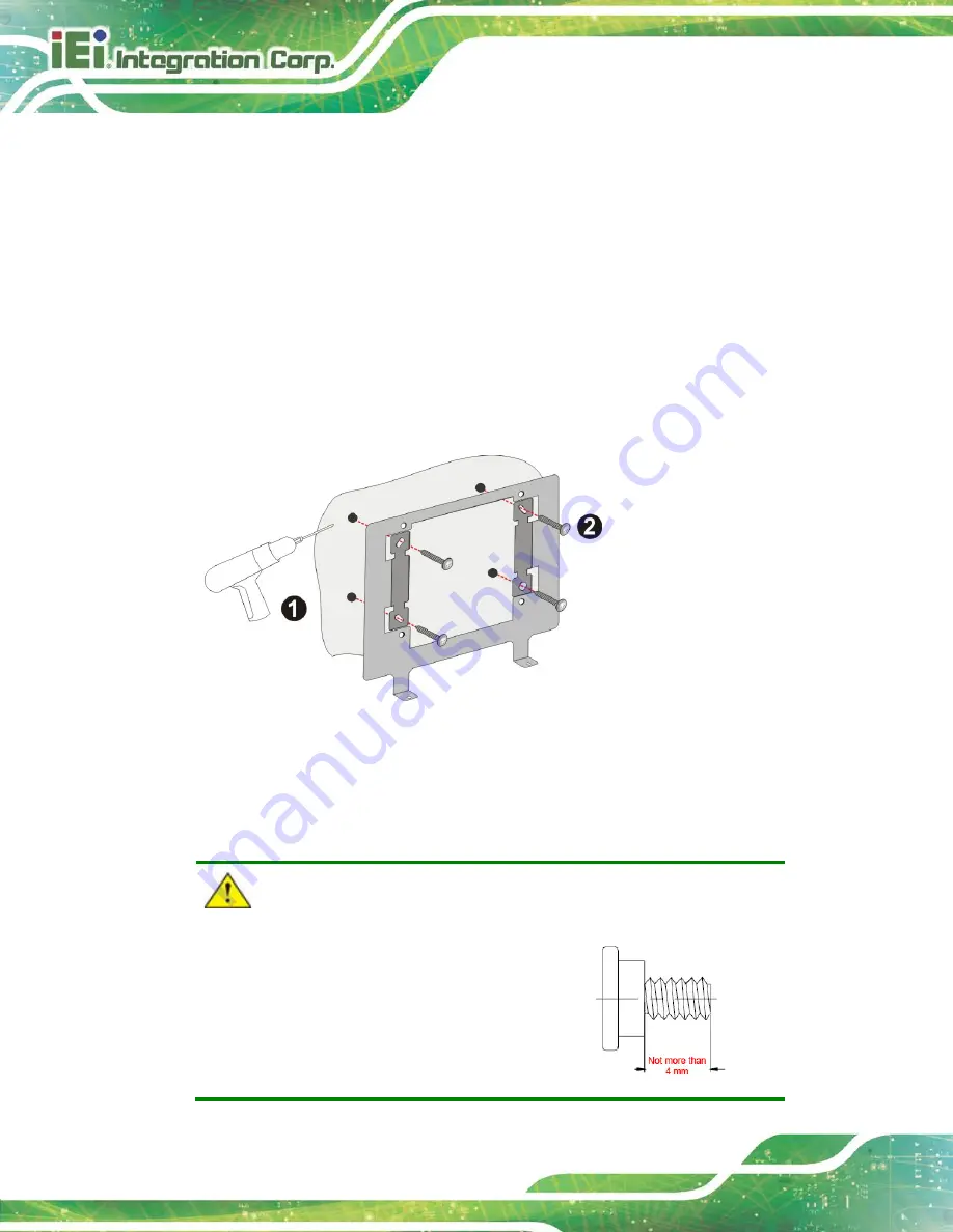
Step 1:
Select a location on the wall for the wall-mounting bracket. Carefully mark the
locations of the screw holes of the wall mounting bracket on the mounting area.
Drill the pilot holes at the marked locations (
).
Step 2:
Secure the mounting bracket to the wall by inserting the retention screws into
the four pilot holes and tightening them (
).
Figure 3-4: Wall Mounting Bracket Installation
Step 3:
Insert the four mounting screws (M4*6) came with the panel PC into the four
screw holes on the mounting bracket and tighten until the screw shank is
secured (
).
CAUTION:
Please use the M4 screws provided in
the package for the mounting screws. If
the screw is missing, the thread depth of
the replacement screw should be not
more than 4 mm.
Содержание IOVU-210AR-RK39
Страница 2: ...IOVU 210AR RK39 Panel PC Page ii Revision Date Version Changes November 8 2018 1 00 Initial release ...
Страница 9: ...IOVU 210AR RK39 Panel PC Page 1 Chapter 1 1 Introduction ...
Страница 16: ...IOVU 210AR RK39 Panel PC Page 8 Chapter 2 2 Unpacking ...
Страница 19: ...IOVU 210AR RK39 Panel PC Page 11 Chapter 3 3 Installation ...
Страница 36: ...IOVU 210AR RK39 Panel PC Page 28 Chapter 4 4 Android OS ...
Страница 44: ...IOVU 210AR RK39 Panel PC Page 36 Figure 4 8 Notification List and System Status ...
Страница 45: ...IOVU 210AR RK39 Panel PC Page 37 Appendix A A Regulatory Compliance ...
Страница 50: ...IOVU 210AR RK39 Panel PC Page 42 Appendix B B Safety Precautions ...
Страница 55: ...IOVU 210AR RK39 Panel PC Page 47 Appendix C C Hazardous Materials Disclosure ...


