IDS-310-AL Embedded System
Page 15
3.3 Bottom Surface Removal
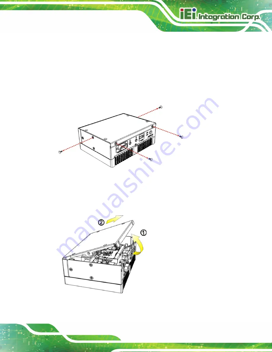
Before internal devices can be installed, the bottom surface must be removed. To remove
the bottom surface, please follow the steps below:
Step 1:
Remove the bottom surface retention screws. The bottom surface is secured to
the chassis with four (4) retention screws (
). All four (4) screws must
be removed.
Figure 3-1: Bottom Surface Retention Screws
Step 2:
Gently lift and remove the bottom surface from the IDS-310-AL.
Step 0:
Figure 3-2: Bottom Surface Removal
Содержание IDS-310-AL
Страница 2: ...IDS 310 AL Embedded System Page II Revision Date Version Changes March 13 2020 1 00 Initial release...
Страница 12: ...IDS 310 AL Embedded System Page XII Figure 5 2 SO DIMM Installation 70 Figure 6 1 Main Board Layout Diagram 72...
Страница 15: ...IDS 310 AL Embedded System Page 1 Chapter 1 1 Introduction...
Страница 22: ...IDS 310 AL Embedded System Page 8 1 7 1 IDS 310 AL J1 Dimensions Figure 1 6 IDS 310 AL J1 Dimensions mm...
Страница 23: ...IDS 310 AL Embedded System Page 9 Chapter 2 2 Unpacking...
Страница 26: ...IDS 310 AL Embedded System Page 12 Chapter 3 3 Installation...
Страница 37: ...IDS 310 AL Embedded System Page 23 Figure 3 16 Hook Onto Mounting Bracket...
Страница 47: ...IDS 310 AL Embedded System Page 33 Chapter 4 4 BIOS...
Страница 81: ...IDS 310 AL Embedded System Page 67 Chapter 5 5 Maintenance...
Страница 85: ...IDS 310 AL Embedded System Page 71 Chapter 6 6 Interface Connectors...
Страница 93: ...IDS 310 AL Embedded System Page 79 Appendix A A Regulatory Compliance...
Страница 98: ...IDS 310 AL Embedded System Page 84 Appendix B B Safety Precautions...
Страница 104: ...IDS 310 AL Embedded System Page 90 Appendix C C BIOS Menu Options...
Страница 107: ...IDS 310 AL Embedded System Page 93 Appendix D D Watchdog Timer...
Страница 110: ...IDS 310 AL Embedded System Page 96 Appendix E E Error Beep Code...
Страница 112: ...IDS 310 AL Embedded System Page 98 Appendix F F Hazardous Materials Disclosure...


