HYPER-BT
Page 33
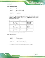
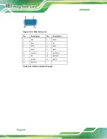
Pin
Description
Pin
Description
1
VCC
2
GND
3
DATA2_N
4
DATA3_P
5
DATA2_P
6
DATA3_N
7
GND
8
VCC
Table 3-18: USB Connector Pinouts
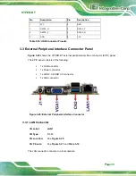
3.3 External Peripheral Interface Connector Panel
shows the HYPER-BT external peripheral interface connector (EPIC) panel.
The EPIC panel consists of the following:
1 x LAN connector
1 x Power connector
1 x USB 2.0 & USB 3.0 connector
1 x VGA connector
Figure 3-20: External Peripheral Interface Connector
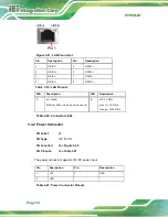
3.3.1 LAN Connector
CN Label:
LAN1
CN Type:
RJ-45
CN Location:
See
CN Pinouts:
See
and
The LAN connector connects to a local network.
Содержание HYPER-BT-E38 1 Series
Страница 10: ......
Страница 11: ...HYPER BT Page 1 1 Introduction Chapter 1 ...
Страница 14: ...HYPER BT Page 4 1 5 Dimensions The dimensions of the board are listed below Figure 1 3 Dimensions mm ...
Страница 19: ...HYPER BT Page 9 2 Unpacking Chapter 2 ...
Страница 23: ...HYPER BT Page 13 3 Connectors Chapter 3 ...
Страница 47: ...HYPER BT Page 37 4 Installation Chapter 4 ...
Страница 56: ...HYPER BT Page 46 5 BIOS Chapter 5 ...
Страница 84: ...HYPER BT Page 74 Appendix A A Regulatory Compliance ...
Страница 86: ...HYPER BT Page 76 B Product Disposal Appendix B ...
Страница 88: ...HYPER BT Page 78 Appendix C C BIOS Menu Options ...
Страница 91: ...HYPER BT Page 81 Appendix D D Error Beep Code ...
Страница 93: ...HYPER BT Page 83 Appendix E E Hazardous Materials Disclosure ...

