


DRPC-120-BTi Embedded System
Page 86
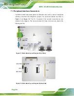
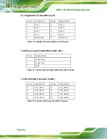
7.1 Peripheral Interface Connectors
The DRPC-120-BTi embedded system motherboard comes with a number of peripheral
interface connectors and configuration jumpers. The connector locations are shown in
and
. The Pin 1 locations of the on-board connectors are also
indicated in the diagrams. The connector pinouts for these connectors are listed in the
following sections.
Figure 7-1:
Main Board Layout Diagram (Front Side)
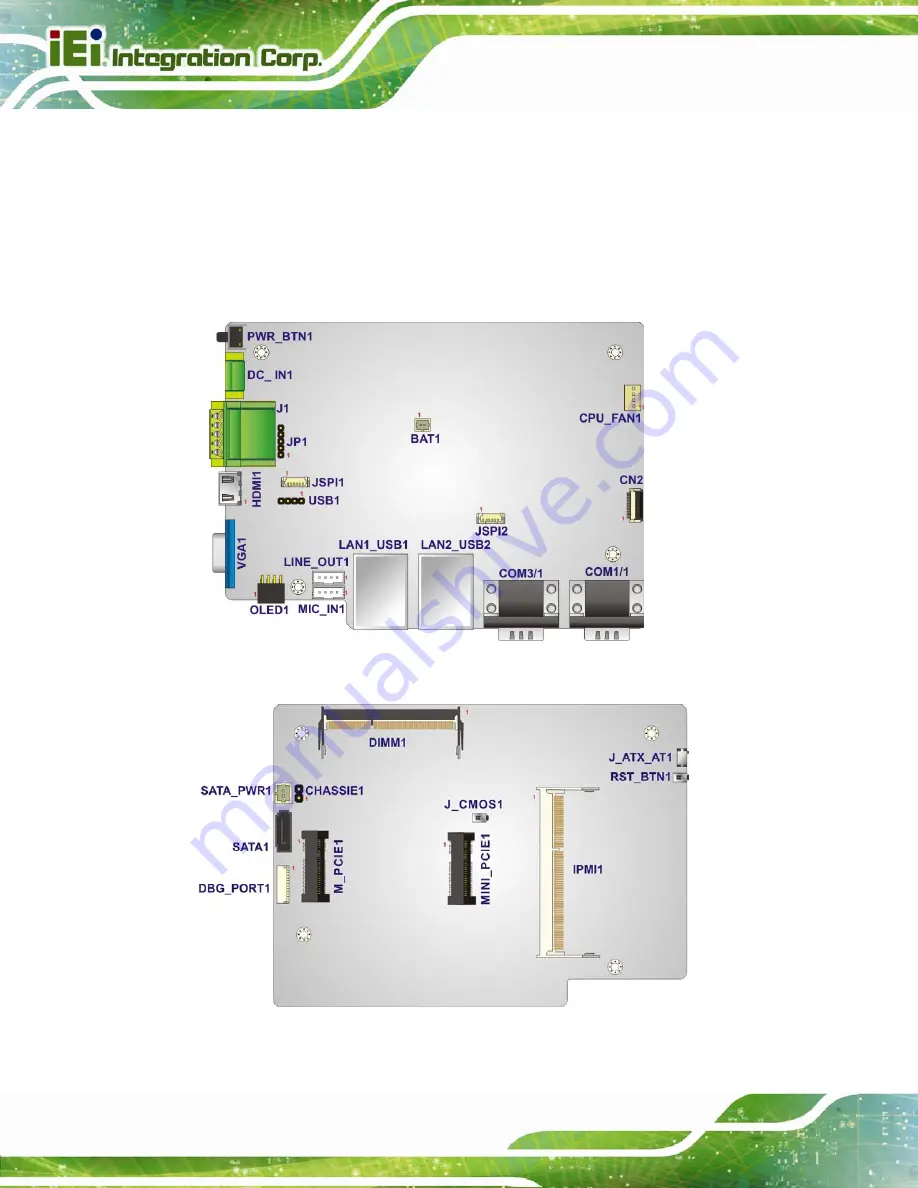
Figure 7-2: Main Board Layout Diagram (Solder Side)
Содержание DRPC-120-BT
Страница 12: ......
Страница 13: ...DRPC 120 BTi Embedded System Page 1 Chapter 1 1 Introduction...
Страница 23: ...DRPC 120 BTi Embedded System Page 11 Chapter 2 2 Unpacking...
Страница 28: ...DRPC 120 BTi Embedded System Page 16 Chapter 3 3 Installation...
Страница 49: ...DRPC 120 BTi Embedded System Page 37 Chapter 4 4 System Maintenance...
Страница 53: ...DRPC 120 BTi Embedded System Page 41 Chapter 5 5 BIOS...
Страница 86: ...DRPC 120 BTi Embedded System Page 74 Chapter 6 6 Programming OLED for DRPC 120 BTi E5 OLED...
Страница 97: ...DRPC 120 BTi Embedded System Page 85 Chapter 7 7 Interface Connectors...
Страница 109: ...DRPC 120 BTi Embedded System Page 97 13 HSYNC 14 VSYNC 15 DDCCLK Table 7 24 VGA Connector VGA1 Pinouts...
Страница 110: ...DRPC 120 BTi Embedded System Page 98 Appendix A A Safety Precautions...
Страница 115: ...DRPC 120 BTi Embedded System Page 103 Appendix B B Digital I O Interface...
Страница 118: ...DRPC 120 BTi Embedded System Page 106 Appendix C C Hazardous Materials Disclosure...


