AFL3-W07A-BT-N1 Panel PC
Page 80
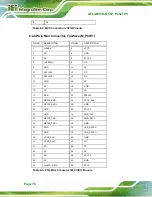
4 GND
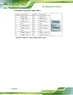
Table 6-13: Webcam Connector (CAM_USB1) Pinouts
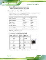
6.3 External Interface Panel Connectors
The table below lists the rear panel connectors on the AFL2MB-15A motherboard. Pinouts
of these connectors can be found in the following sections.
Connector
Type
Label
Ethernet connector
RJ-45
LAN1
Ethernet connector
RJ-45
LAN2
Power button
Push button
PB_SW1
Power connector
Power jack
CN5
RS-232 serial port
D-sub 9
COM1
RS-232 serial port
D-sub 9
COM2
USB 3.0 connectors
USB 3.0 port
USB_CON1
Table 6-14: Rear Panel Connectors
6.3.1 Ethernet Connectors (LAN1 & LAN2)
PIN NO.
DESCRIPTION
PIN NO.
DESCRIPTION
1 MDI0+
10 MDI3-
2 MDI0-
11 +3.3Vsus
3 MDI1+
12 ACT-1
4 MDI1-
13 LINNK1000
+3.3sus
5 N/A
14 LINNK1000
+3.3sus
6 N/A
15 GND
7 MDI2+
16 GND
8 MDI2-
17 N/A
9 MDI3+
18 N/A
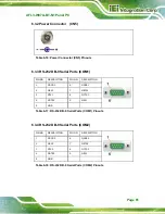
Table 6-15: Ethernet Connectors (LAN1 & LAN2) Pinouts
Содержание AFL3-W07A-BT-N1
Страница 12: ......
Страница 13: ...AFL3 W07A BT N1 Panel PC Page 1 1 Introduction Chapter 1...
Страница 17: ...AFL3 W07A BT N1 Panel PC Page 5 Figure 1 4 Bottom Panel...
Страница 21: ...AFL3 W07A BT N1 Panel PC Page 9 2 Unpacking Chapter 2...
Страница 25: ...AFL3 W07A BT N1 Panel PC Page 13 3 Installation Chapter 3...
Страница 50: ...AFL3 W07A BT N1 Panel PC Page 38 4 BIOS Setup Chapter 4...
Страница 78: ...AFL3 W07A BT N1 Panel PC Page 66 5 System Maintenance Chapter 5...
Страница 84: ...AFL3 W07A BT N1 Panel PC Page 72 6 Interface Connectors Chapter 6...
Страница 95: ...AFL3 W07A BT N1 Panel PC Page 83 A Safety Precautions Appendix A...
Страница 100: ...AFL3 W07A BT N1 Panel PC Page 88 B BIOS Menu Options Appendix B...
Страница 103: ...AFL3 W07A BT N1 Panel PC Page 91 Appendix C C Watchdog Timer...
Страница 106: ...AFL3 W07A BT N1 Panel PC Page 94 D Hazardous Materials Disclosure Appendix D...


