


AFL3-W10A/12A/W15A-BT Panel PC
Page 48
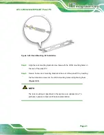
Step 5:
Align the V-Stand screw holes with the pilot holes on the mounting area. Mount
the V-Stand by inserting the retention screws into the four pilot holes and
tightening them.
Step 6:
Adjust the V-Stand to have a best viewing angle to operate the system.
S
te
p
0
:
Figure 3-34: Secure V-Stand to Mounting Area
Содержание AFL3-12A-BT
Страница 15: ...AFL3 W10A 12A W15A BT Panel PC Page 1 1 Introduction Chapter 1...
Страница 28: ...AFL3 W10A 12A W15A BT Panel PC Page 14 2 Unpacking Chapter 2...
Страница 33: ...AFL3 W10A 12A W15A BT Panel PC Page 19 3 Installation Chapter 3...
Страница 69: ...AFL3 W10A 12A W15A BT Panel PC Page 55 4 BIOS Setup Chapter 4...
Страница 101: ...AFL3 W10A 12A W15A BT Panel PC Page 87 5 System Maintenance Chapter 5...
Страница 106: ...AFL3 W10A 12A W15A BT Panel PC Page 92 6 Interface Connectors Chapter 6...
Страница 121: ...AFL3 W10A 12A W15A BT Panel PC Page 107 Appendix A A Regulatory Compliance...
Страница 126: ...AFL3 W10A 12A W15A BT Panel PC Page 112 B Safety Precautions Appendix B...
Страница 132: ...AFL3 W10A 12A W15A BT Panel PC Page 118 C BIOS Menu Options Appendix C...
Страница 135: ...AFL3 W10A 12A W15A BT Panel PC Page 121 Appendix D D Watchdog Timer...
Страница 138: ...AFL3 W10A 12A W15A BT Panel PC Page 124 Appendix E E Error Beep Code...
Страница 140: ...AFL3 W10A 12A W15A BT Panel PC Page 126 Appendix F F Hazardous Materials Disclosure...


