AFL3-W10A/12A/W15A-BT Panel PC
Page 39
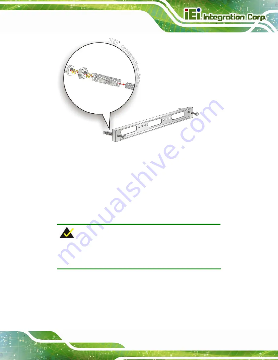
Figure 3-22: Panel Mounting Kit Installation
Step 6:
Align the panel mounting bracket screw holes with the VESA mounting holes on
the rear of the panel PC.
Step 7:
Secure the two panel mounting brackets to the rear of the panel PC by inserting
the four retention screws into the VESA mounting holes and tightening them
(
Figure 3-23
).
S
te
p
0
:
NOTE:
The panel mounting kit described in this section is an optional item. To
purchase it, please contact an IEI sales representative.


