AFL-HM55 Series Panel PC
Page 49
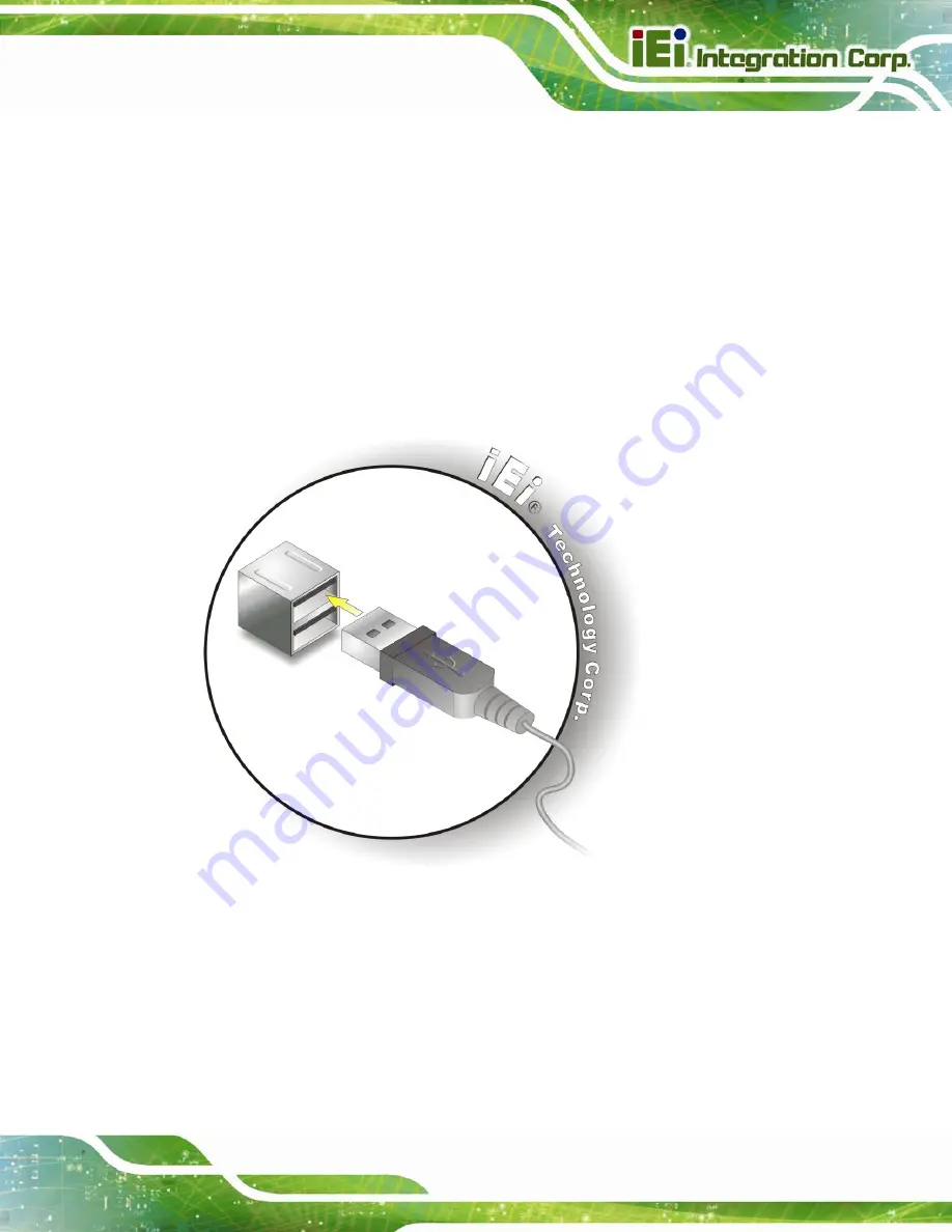
3.11.3 USB Device Connection
There are four external USB 2.0 connectors. All connectors are perpendicular to the
AFL-HM55 Series. To connect a USB 2.0 or USB 1.1 device, please follow the instructions
below.
Step 1:
Located the USB connectors
. The locations of the USB connectors are shown
in
Chapter 2
.
Step 2:
Align the connectors.
Align the USB device connector with one of the
connectors on the bottom panel. See
Figure 3-28: USB Device Connection
Step 3:
Insert the device connector.
Once aligned, gently insert the USB device
connector into the onboard connector.
Содержание AFL-HM55
Страница 12: ...AFL HM55 Series Panel PC Page I 1 Introduction Chapter 1 ...
Страница 23: ...AFL HM55 Series Panel PC Page 12 2 Unpacking Chapter 2 ...
Страница 29: ...AFL HM55 Series Panel PC Page 18 3 Installation Chapter 3 ...
Страница 63: ...AFL HM55 Series Panel PC Page 52 Point of Sale POS Advertising terminal ...
Страница 64: ...AFL HM55 Series Panel PC Page 53 4 System Maintenance Chapter 4 ...
Страница 70: ...AFL HM55 Series Panel PC Page 59 5 BIOS Setup Chapter 5 ...
Страница 96: ...AFL HM55 Series Panel PC Page 85 6 Software Drivers Chapter 6 ...
Страница 123: ...AFL HM55 Series Panel PC Page 112 A Safety Precautions Appendix A ...
Страница 127: ...AFL HM55 Series Panel PC Page 116 Appendix B B ALC892 Digital Microphone Configuration ...
Страница 131: ...AFL HM55 Series Panel PC Page 120 C BIOS Configuration Options Appendix C ...
Страница 134: ...AFL HM55 Series Panel PC Page 123 D Watchdog Timer Appendix D ...
Страница 137: ...AFL HM55 Series Panel PC Page 126 E Hazardous Materials Disclosure Appendix E ...


