background image


AFL-F08A-N270 Panel PC

Page 70 

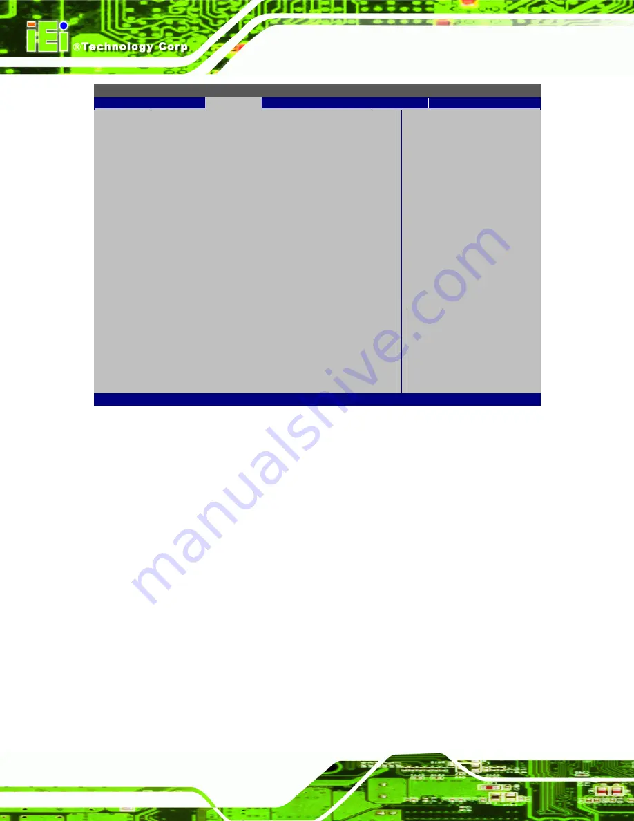
BIOS SETUP UTILITY 

Main 

Advanced 

PCIPNP 

Boot 

Security

Chipset

Exit 


Advanced PCI/PnP Settings 

⎯⎯⎯⎯⎯⎯⎯⎯⎯⎯⎯⎯⎯⎯⎯⎯⎯⎯⎯⎯⎯⎯⎯⎯⎯⎯⎯⎯⎯⎯⎯


WARNING: Setting wrong values in below sections 
           may  cause  system  to  malfunction 

IRQ3  

[Reserved] 

IRQ4  

[Reserved] 

IRQ5  

[Available] 

IRQ7  

[Available] 

IRQ9  

[Available] 

IRQ10  

[Reserved] 

IRQ11  

[Reserved] 

IRQ14  

[Available] 

IRQ15  

[Available] 

 
DMA Channel 0 

[Available] 

DMA Channel 1 

[Available] 

DMA Channel 3 

[Available] 

DMA Channel 5 

[Available] 

DMA Channel 6 

[Available] 

DMA Channel 7 

[Available] 

 
Reserved Memory Size 

[Disabled] 


ÅÆ

 Select 

Screen 


 Select 

Item 

Enter Go to SubScreen 
F1 General 

Help 

F10 

Save and Exit 

ESC Exit 
 

v02.61 ©Copyright 1985-2006, American Megatrends, Inc. 

BIOS Menu 13: PCI/PnP Configuration 

Î


IRQ#  

Use the 

IRQ# 

address to specify what IRQs can be assigned to a particular peripheral 

device. 

Î


Available  

The specified IRQ is available to be used by 

PCI/PnP devices 

Î


Reserved  

The specified IRQ is reserved for use by Legacy ISA 

devices 

Available IRQ addresses are: 

ƒ

 IRQ3 

ƒ

 IRQ4 

ƒ

 IRQ5 

ƒ

 IRQ7 

Содержание AFL-F08A-N270

Страница 1: ...nel PC Page i IEI Technology Corp User Manual MODEL AFL F08A N270 Fanless All in one Panel PC with 1 6 GHz Intel Atom CPU TFT LCD Wireless LAN Touch Screen RS 232 422 485 and IP 64 Protection Rev 2 40...

Страница 2: ...Added Section 5 Interface Connectors Added Appendix B ALC892 Digital Microphone Configuration 17 July 2012 2 21 Added Section 3 1 3 1 3 Function Keys 22 February 2012 2 20 Updated for R22 version opt...

Страница 3: ...s arising out of the use or inability to use the product or documentation even if advised of the possibility of such damages This document contains proprietary information protected by copyright All r...

Страница 4: ...AUTIONS 15 3 3 INSTALLATION AND CONFIGURATION STEPS 16 3 4 REMOVING THE BACK COVER 16 3 5 CF CARD INSTALLATION 18 3 6 INTERNAL COVER REMOVAL 19 3 7 JUMPER SETTINGS 20 3 7 1 Access the Jumpers 20 3 7 2...

Страница 5: ...11 POWERING OFF THE SYSTEM 41 4 SYSTEM MAINTENANCE 42 4 1 SYSTEM MAINTENANCE INTRODUCTION 43 4 2 ANTI STATIC PRECAUTIONS 43 4 3 TURN OFF THE POWER 44 4 4 OPENING THE SYSTEM 44 4 5 REPLACING COMPONENT...

Страница 6: ...5 7 2 South Bridge Configuration 79 5 8 EXIT 80 6 INTERFACE CONNECTORS 82 6 1 PERIPHERAL INTERFACE CONNECTORS 83 6 2 INTERNAL PERIPHERAL CONNECTORS 84 6 2 1 Audio Line out Connector CN8 85 6 2 2 Audi...

Страница 7: ...6 4 PRECONFIGURED JUMPER SETTINGS 97 6 4 1 Backlight Voltage Selection Jumper J_BL1 97 6 4 2 Inverter Power Selection Jumper JP12 97 6 4 3 LVDS Panel Voltage Selection Jumper J_VLVDS1 98 6 4 4 MCU LCD...

Страница 8: ...0 C 6 3 Configure One Key Recovery Server Settings 141 C 6 4 Start the DHCP TFTP and HTTP 142 C 6 5 Create Shared Directory 142 C 6 6 Setup a Client System for Auto Recovery 143 C 7 OTHER INFORMATION...

Страница 9: ...AFL F08A N270 Panel PC Page ix G TERMINOLOGY 161...

Страница 10: ...r CMOS Jumper 23 Figure 3 9 COM1 and COM3 Pin 9 Setting Jumper Locations 24 Figure 3 10 COM3 RX Function Select Jumper Location 25 Figure 3 11 COM3 TX Function Select Jumper Pinout Locations 26 Figure...

Страница 11: ...Tool 113 Figure C 3 Recovery Tool Setup Menu 113 Figure C 4 Command Prompt 114 Figure C 5 Partition Creation Commands 115 Figure C 6 Launching the Recovery Tool 117 Figure C 7 Manual Recovery Environ...

Страница 12: ...tinue 128 Figure C 30 Partitions for Linux 130 Figure C 31 Manual Recovery Environment for Linux 131 Figure C 32 Access menu lst in Linux Text Mode 131 Figure C 33 Recovery Tool Menu 132 Figure C 34 R...

Страница 13: ...l Port Select Jumper Settings 27 Table 3 11 CompactFlash Setup Jumper Settings 28 Table 3 12 COM1 Connector Pinouts 38 Table 3 13 COM3 Connector Pinouts 39 Table 5 1 BIOS Navigation Keys 51 Table 6 1...

Страница 14: ...ctor LAN1 LAN2 Pinouts 95 Table 6 26 Power Connector CN5 Pinouts 95 Table 6 27 RS 232 Serial Ports COM1 Pinouts 95 Table 6 28 COM3 Connector Pinouts 96 Table 6 29 SATA Connector SATA2 Pinouts 96 Table...

Страница 15: ...IOS Menu 8 Power Configuration 62 BIOS Menu 9 General ACPI Configuration 63 BIOS Menu 10 APM Configuration 64 BIOS Menu 11 Remote Access Configuration 66 BIOS Menu 12 USB Configuration 68 BIOS Menu 13...

Страница 16: ...AFL F08A N270 Panel PC Page 1 Chapter 1 1 Introduction...

Страница 17: ...ormed by simply using both fingers to indicate movements and actions At the heart of the system is the 1 6 GHz Intel Atom N270 processor offering low power in a powerful package The chipset is rounded...

Страница 18: ...MHz DDR2 SDRAM SO DIMM pre installed supports up to 2 0 GB 533 400 MHz DDR2 SDRAM 802 11 b g n wireless module Two USB 2 0 ports IP 64 compliant front panel Touch screen multitouch or standard RoHS co...

Страница 19: ...y lock the keys light up Then follow the descriptions below to control the system Function Key Description Power on off Control system power on off Press for 5 seconds to turn on or turn off the syste...

Страница 20: ...O Interface Panel The I O interface panel located on the bottom of the AFL F08A N270 has the following I O interface connectors 1 x Audio connector 1 x 12 V DC In connector 1 x External SATA connector...

Страница 21: ...pecifications for the AFL F08A N270 systems are listed in 77Table 1 2 Specification Description LCD Size 8 Max Resolution 800 x 600 Contrast Ratio 500 1 Brightness cd m2 250 LCD Color 262K Pixel Pitch...

Страница 22: ...Dimensions W x H x D 234 mm x 177 mm x 43 mm Operation Temperature 10 C 50 C Storage Temperature 20 C 60 C Net weight 1 8 kg IP level front panel IP 64 EMC CE FCC and CCC Safety CB Touch Screen AFL F0...

Страница 23: ...AFL F08A N270 Panel PC Page 8 1 8 Dimensions The dimensions are shown below Figure 1 5 Main Dimensions...

Страница 24: ...AFL F08A N270 Panel PC Page 9 Figure 1 6 Rear Dimensions...

Страница 25: ...AFL F08A N270 Panel PC Page 10 Chapter 2 2 Unpacking...

Страница 26: ...rp pair of scissors that seals the top side of the external second box Step 2 Open the external second box Step 3 Use box cutters a knife or a sharp pair of scissors that seals the top side of the int...

Страница 27: ...70 Panel PC Page 12 Quantity Item Image 1 Power adapter 1 Power cord 1 Power transfer cord 1 Screw kit 1 Touch pen 1 User manual CD and driver CD Table 2 1 Packing List Item Image Panel mounting kit P...

Страница 28: ...3 Item Image Wall mounting kit P N AFLWK 08 Stand P N STAND A08 Arm P N ARM 11 RS Arm P N ARM 31 RS Table 2 2 Optional Items If any of these items are missing or damaged contact the distributor or sal...

Страница 29: ...AFL F08A N270 Panel PC Page 14 Chapter 3 3 Installation...

Страница 30: ...lp to prevent ESD from damaging the board Self grounding Before handling the board touch any grounded conducting material During the time the board is handled frequently touch any conducting materials...

Страница 31: ...lowing installation steps must be followed Step 1 Unpack the system Step 2 Install a CF card Step 3 Configure the system Step 4 Connect peripheral devices Step 5 Mount the system Step 0 3 4 Removing t...

Страница 32: ...the cover off the flat panel PC Figure 3 1 Back Cover Retention Screws Step 2 Use a screwdriver to gently pry the edges of the system loose Figure 3 2 Pry The Rear Cover Off Step 3 The cover will come...

Страница 33: ...ve the cover plate and install the CompactFlash card follow the instructions below Step 1 Undo the CompactFlash cover fastening screw Figure 3 3 CompactFlash Card Cover Screw Step 2 Slide the CompactF...

Страница 34: ...internal parts the internal aluminum cover needs to be removed To remove this cover please follow the steps below Step 1 Undo the fastening screws indicated by the arrows and circles below Figure 3 5...

Страница 35: ...plastic clip and to OPEN a jumper means removing the plastic clip from a jumper The following jumpers and switches can be changed after removing the rear cover Description Label Type Clear CMOS J_COM...

Страница 36: ...Name Label Type Backlight voltage selection J_BL1 3 pin header Inverter power selection JP12 6 pin header LVDS voltage selection J_VLVDS1 3 pin header MCU LCD type selection JP14 4 pin header MCU PWM...

Страница 37: ...mper clears the CMOS data and resets the system BIOS information To do this use the jumper cap to close the pins for a few seconds then remove the jumper clip If the CMOS Settings Wrong message is dis...

Страница 38: ...Port Pin 9 Select Jumper Label JP8 and JP10 Jumper Settings See 77Table 3 4 Jumper Location See 77Figure 3 9 Two jumpers JP8 and JP10 configure pin 9 on COM1 and COM3 DB 9 connectors Pin 9 on the COM1...

Страница 39: ...Pin 9 Setting jumper locations are shown in 77Figure 3 9 below Figure 3 9 COM1 and COM3 Pin 9 Setting Jumper Locations 3 7 5 1 COM3 RS 422 and RS 485 Pinouts The pinouts for RS 422 and RS 485 operatio...

Страница 40: ...used by the RX serial communications port COM3 as RS 232 RS 422 or RS 485 The COM3 RX Function Select jumper settings are shown in 77Table 3 8 COM3 RX Function Select Description Short 1 2 DET BIOS RS...

Страница 41: ...n on COM3 serial port connector as RS 422 as an RS 485 The COM3 TX Function Select jumper selection options are shown in 77Table 3 9 COM3 TX Function Select Description Short 1 3 RS 422 TX Short 2 4 R...

Страница 42: ...second serial communications port COM3 as RS 232 RS 422 or RS 485 The COM3 RS 232 422 485 Serial Port Select settings are shown in 77Table 3 10 RS 232 485 Select Description Short 1 2 RS 232 Default...

Страница 43: ...abel JCF1 Jumper Type 2 pin header Jumper Settings See 7Table 3 11 Jumper Location See 7Figure 3 13 The CompactFlash slot is connected through an IDE connection This jumper sets the CompactFlash card...

Страница 44: ...ions below 3 8 1 Wall Mounting To mount the system onto the wall please follow the steps below Step 1 Select the location on the wall for the wall mounting bracket Step 2 Carefully mark the locations...

Страница 45: ...the real panel and tighten until the screw shank is secured against the rear panel 77Figure 3 15 WARNING Please use the M4 screws provided in the wall mount kit for the rear panel If the screw is miss...

Страница 46: ...securely in the slotted holes 77Figure 3 15 Ensure that all four of the mounting screws fit snuggly into their respective slotted holes NOTE In the diagram below the bracket is already installed on t...

Страница 47: ...t panel PC Take care that the panel section that is cut out is smaller than the overall size of the frame but larger than the rear part of the system body Step 12 Slide the system through the hole unt...

Страница 48: ...rm is a separately purchased item Please correctly mount the arm onto the surface it uses as a base To do this refer to the installation documentation that came with the mounting arm NOTE When purchas...

Страница 49: ...8 4 Cabinet and Rack Installation The AFL F08A N270 can be installed into a cabinet or rack The installation procedures are similar to the panel mounting installation To do this please follow the step...

Страница 50: ...anel PC behind the ABS PC plastic frame Step 3 Tighten the screws that pass through the rack mounting clamps until the plastic caps at the front of all the screws are firmly secured to the bracket 77F...

Страница 51: ...tors This section provides and overview of the connectors on the bottom panel 3 9 1 LAN Connection There are two external RJ 45 LAN connectors The RJ 45 connector enables connection to an external net...

Страница 52: ...ial Device Connection The AFL F08A N270 has two male DB 9 connectors on the bottom panel for serial devices to be connected Follow the steps below to connect a serial device to the AFL F08A N270 Step...

Страница 53: ...ice connector to the external interface by tightening the two retention screws on either side of the connector Step 0 3 9 2 1 COM1 Pinouts The pinouts for COM1 are listed in the table below Pin Descri...

Страница 54: ...TR3 5 GND 6 NDSRB RX 7 NRTSB RX 8 NCTS3 9 COM_RI3 10 GND Table 3 13 COM3 Connector Pinouts 3 9 3 USB Device Connection There are two external USB connectors All connectors are perpendicular to the AFL...

Страница 55: ...0 Powering On the System WARNING Make sure a power supply with the correct input voltage is being fed into the system Incorrect voltages applied to the system may cause damage to the internal electron...

Страница 56: ...he System To power off the AFL F08A N270 using the function key please follow the steps below Step 1 Press the power on off function key on the front panel to wake the function keys Step 2 Press the p...

Страница 57: ...AFL F08A N270 Panel PC Page 42 Chapter 4 4 System Maintenance...

Страница 58: ...harge ESD can cause serious damage to electronic components including the AFL F08A N270 Dry climates are especially susceptible to ESD It is therefore critical that whenever the AFL F08A N270 is acces...

Страница 59: ...or fatal injury to the user Before any maintenance procedures are carried out on the system make sure the system is turned off 4 4 Opening the System Remove the rear cover as shown in Section 773 4 R...

Страница 60: ...from the socket Step 3 Grasp the SO DIMM by the edges and carefully pull it out of the socket Step 4 Install the new SO DIMM by pushing it into the socket at an angle 77Figure 4 2 Step 5 Push the SO D...

Страница 61: ...te and install the CompactFlash card follow the instructions below Step 1 Undo the CompactFlash cover fastening screw Figure 4 3 CompactFlash Card Cover Step 2 Slide the CompactFlash card into the slo...

Страница 62: ...ntent of the CD may vary throughout the life cycle of the product and is subject to change without prior notice Visit the IEI website or contact technical support for the latest updates Installation i...

Страница 63: ...Page 48 Figure 4 5 Drivers Step 4 Install the drivers as required Step 0 NOTE When installing the Wireless LAN card driver make sure to select the RT3090 folder which indicates the WLAN card model in...

Страница 64: ...AFL F08A N270 Panel PC Page 49 Chapter 5 5 BIOS...

Страница 65: ...efore the DELETE key is pressed restart the computer and try again 5 1 2 Using Setup Use the arrow keys to highlight items press ENTER to select use the PageUp and PageDown keys to change entries pres...

Страница 66: ...to the system configuration is made CMOS defaults Use the jumper described in Section 773 7 4 5 1 5 BIOS Menu Bar The menu bar on top of the BIOS screen has the following main items Main Changes the b...

Страница 67: ...t v02 61 Copyright 1985 2006 American Megatrends Inc BIOS Menu 1 Main System Overview The System Overview lists a brief summary of different system components The fields in System Overview cannot be c...

Страница 68: ...utes and seconds System Date xx xx xx Use the System Date option to set the system date Manually enter the day month and year 5 3 Advanced Use the Advanced menu to configure the CPU and peripheral dev...

Страница 69: ...ced 5 3 1 CPU Configuration Use the CPU Configuration menu to view detailed CPU specifications and configure the CPU BIOS SETUP UTILITY Main Advanced PCIPNP Boot Security Chipset Exit Configure Advanc...

Страница 70: ...Channels SATA Pri PATA Sec Primary IDE Master Not Detected Primary IDE Slave Not Detected Secondary IDE Master Not Detected Secondary IDE Slave Not Detected Select Screen Select Item Enter Go to SubSc...

Страница 71: ...ects the presence of IDE devices BIOS displays the status of the auto detected IDE devices The following IDE devices are detected and are shown in the IDE Configuration menu Primary IDE Master Primary...

Страница 72: ...he selected IDE disk drive The drive parameters are listed as follows Device Lists the device type e g hard disk CD ROM etc Type Indicates the type of devices a user can manually select LBA Mode Indic...

Страница 73: ...nnel The BIOS does not attempt to search for other types of IDE disk drives on the specified channel ARMD This option specifies an ATAPI Removable Media Device These include but are not limited to ZIP...

Страница 74: ...uto DEFAULT BIOS auto detects the PIO mode Use this value if the IDE disk drive support cannot be determined 0 PIO mode 0 selected with a maximum transfer rate of 3 3 MB s 1 PIO mode 1 selected with a...

Страница 75: ...ables or disable 32 bit data transfers Disabled Prevents the BIOS from using 32 bit data transfers Enabled DEFAULT Allows BIOS to use 32 bit data transfers on supported hard disk drives 5 3 3 Super IO...

Страница 76: ...ets the port address of serial port 3 Disabled 3E8 DEFAULT 2E8 2F0 2E0 Serial Port 3 IRQ IRQ4 Sets the interrupt address of serial port 3 10 11 DEFAULT Select RS232 or RS422 RS485 RS232 Sets the commu...

Страница 77: ...792 V 5VSB 4 919 V VBAT 3 232 V Select Screen Select Item Enter Go to SubScreen F1 General Help F10 Save and Exit ESC Exit v02 61 Copyright 1985 2006 American Megatrends Inc BIOS Menu 7 Hardware Healt...

Страница 78: ...F10 Save and Exit ESC Exit v02 61 Copyright 1985 2006 American Megatrends Inc BIOS Menu 9 General ACPI Configuration Suspend Mode S1 POS Use the Suspend Mode option to specify the sleep state the syst...

Страница 79: ...u 10 APM Configuration Restore on AC Power Loss Last State Use the Restore on AC Power Loss BIOS option to specify what state the system returns to if there is a sudden loss of power to the system Pow...

Страница 80: ...ent not generated by PCI Express activity Enabled DEFAULT Wake event generated by PCI Express activity Resume On RTC Alarm Disabled Use the Resume On RTC Alarm option to specify the time the system sh...

Страница 81: ...ss Disabled Use the Remote Access option to enable or disable access to the remote functionalities of the system Disabled DEFAULT Remote access is disabled Enabled Remote access configuration options...

Страница 82: ...n is made The following configuration options are available 115200 8 n 1 DEFAULT 57600 8 n 1 38400 8 n 1 19200 8 n 1 09600 8 n 1 NOTE Identical baud rate setting musts be set on the host a management...

Страница 83: ...USB Configuration Module Version 2 24 0 11 4 USB Devices Enabled None USB Functions Enabled USB 2 0 Controller Enabled Legacy USB Support Enabled USB 2 0 Controller Mode HiSpeed Select Screen Select I...

Страница 84: ...board can control the system even when there is no USB driver loaded onto the system Disabled Legacy USB support disabled Enabled DEFAULT Legacy USB support enabled Auto Legacy USB support disabled if...

Страница 85: ...DMA Channel 3 Available DMA Channel 5 Available DMA Channel 6 Available DMA Channel 7 Available Reserved Memory Size Disabled Select Screen Select Item Enter Go to SubScreen F1 General Help F10 Save a...

Страница 86: ...reserved for use by Legacy ISA devices Available DMA Channels are DM Channel 0 DM Channel 1 DM Channel 3 DM Channel 5 DM Channel 6 DM Channel 7 Reserved Memory Size Disabled Use the Reserved Memory Si...

Страница 87: ...1 Boot Settings Configuration Use the Boot Settings Configuration menu 77BIOS Menu 15 to configure advanced system boot options BIOS SETUP UTILITY Main Advanced PCIPNP Boot Security Chipset Exit Boot...

Страница 88: ...M Display Mode Force BIOS Use the AddOn ROM Display Mode option to allow add on ROM read only memory messages to be displayed Force BIOS DEFAULT The system forces third party BIOS to display during sy...

Страница 89: ...ght on the keyboard is lit Boot From LAN Support Disabled Use the BOOT From LAN Support option to enable the system to be booted from a remote system Enabled Can be booted from a remote system through...

Страница 90: ...ds Inc BIOS Menu 16 Security Change Supervisor Password Use the Change Supervisor Password to set or change a supervisor password The default for this option is Not Installed If a supervisor password...

Страница 91: ...cause the system to malfunction BIOS SETUP UTILITY Main Advanced PCIPNP Boot Security Chipset Exit Advanced Chipset Settings WARNING Setting wrong values in below section may cause system to malfuncti...

Страница 92: ...t ESC Exit v02 61 Copyright 1985 2006 American Megatrends Inc BIOS Menu 18 Northbridge Chipset Configuration Memory Hole Disabled Use the Memory Hole option to reserve memory space between 15 MB and 1...

Страница 93: ...aphics memory is reserved as graphics memory If more memory is needed graphics memory is dynamically allocated according to the system and graphics needs DVMT FIXED Memory Maximum DVMT Use the DVMT FI...

Страница 94: ...chipset to be configured BIOS SETUP UTILITY Main Advanced PCIPNP Boot Security Chipset Exit South Bridge Chipset Configuration Audio Controller Auto Select Screen Select Item Enter Go to SubScreen F1...

Страница 95: ...American Megatrends Inc BIOS Menu 20 Exit Save Changes and Exit Use the Save Changes and Exit option to save the changes made to the BIOS options and to exit the BIOS configuration setup program Disca...

Страница 96: ...F08A N270 Panel PC Page 81 Load Failsafe Defaults Use the Load Failsafe Defaults option to load failsafe default values for each of the parameters on the Setup menus F8 key can be used for this operat...

Страница 97: ...AFL F08A N270 Panel PC Page 82 6 Interface Connectors Chapter 6...

Страница 98: ...of peripheral interface connectors and configuration jumpers The connector locations are shown in Figure 6 1 The Pin 1 locations of the on board connectors are also indicated in the diagram below The...

Страница 99: ...The table below shows a list of the peripheral interface connectors on the AFL F08A N270 motherboard Pinouts of these connectors can be found in the following sections Connector Type Label AT ATX swit...

Страница 100: ...nnector 10 pin header JP8 SATA connector SATA connector SATA1 SO DIMM connector SO DIMM connector DIMM1 SPI Flash connector 8 pin header JSPI1 Touch panel connector solder side 9 pin wafer TS1 TTL pan...

Страница 101: ...nnector DMIC1 PIN NO DESCRIPTION 1 AMP_L 2 AMP_L 3 AMP_R 4 AMP_R Table 6 3 Audio Speaker out Connector CN3 Pinouts PIN NO DESCRIPTION 1 MIC_IN_L 2 AGND_AMP 3 MIC_JD 4 MIC1_IN_R Table 6 4 Audio MIC in...

Страница 102: ...4 DATA 5 29 DATA 13 5 DATA 6 30 DATA 14 6 DATA 7 31 DATA 15 7 CE 32 CE2 8 A10 33 VS1 9 OE 34 IOR 10 A9 35 IOW 11 A8 36 WE 12 A7 37 IRQ 13 VCC1 38 VCC2 14 A6 39 CSEL 15 A5 40 VS2 16 A4 41 RESET 17 A3...

Страница 103: ...K2 5 DACB_BLUE 6 V_GND 7 H_SYNC 8 V_GND 9 V_SYNC 10 V_GND 2 10 y y y y y y y y y y 1 9 Table 6 8 CRT Connector CN4 Pinouts 6 2 8 DIO Connector DIO1 PIN NO DESCRIPTION PIN NO DESCRIPTION 1 GND 2 VCC_ 5...

Страница 104: ...Table 6 11 LED Indicator and Button Connector JP2 Pinouts 6 2 11 LVDS Backlight Connector INVERTER1 6 2 12 MCU Connector JP7 PIN NO DESCRIPTION PIN NO DESCRIPTION 1 MCLR 2 5V 3 5V 4 MCU_IR 5 ICSPCLK 6...

Страница 105: ...7 CLKREQ 8 N C 9 GND 10 N C 11 REFCLK 12 N C 13 REFCLK 14 N C 15 GND 16 N C 17 N C 18 GND 19 N C 20 N C 21 GND 22 PERST 23 PERn0 24 VCC3_AUX 25 PERp0 26 GND 27 GND 28 1 5 V 29 GND 30 SMBCLK 31 PETn0 3...

Страница 106: ...RESERVED 50 GND 51 RESERVED 52 VCC3 Table 6 15 PCIe Mini Card Slot CN2 Pinouts 6 2 15 RFID Connector JP8 PIN NO DESCRIPTION PIN NO DESCRIPTION 1 2 5V 3 4 GND 5 6 RX2 7 8 TD2 9 For COM1 Pin 9 setting...

Страница 107: ..._VCC3 27 TFT_G0 8 TTL_HSYNC 28 GND 9 LCD_EN 29 TFT_R5 10 GND 30 TFT_R4 11 GND 31 TFT_R3 12 GND 32 GND 13 TFT_B5 33 TFT_R2 14 TFT_B4 34 TFT_R1 15 TFT_B3 35 TFT_R0 16 GND 36 GND PIN NO 8 Wire 4 Wire 5 W...

Страница 108: ...Connector USB1 PIN NO DESCRIPTION PIN NO DESCRIPTION 1 5Vsus 2 GND 3 D0F 4 D0F 5 D0F 6 D0F 7 GND 8 5Vsus 2 8 y y y y y y y y 1 7 Table 6 21 USB Connector USB1 Pinouts 6 2 21 USB Connector USB2 PIN NO...

Страница 109: ...connector DIN CN5 Reset button Push button CN6 RS 232 serial ports DB 9 COM1 RS 232 422 485 serial port DB 9 COM3 SATA connector SATA connector SATA2 USB 2 0 connectors USB 2 0 port USB3 Table 6 24 R...

Страница 110: ...wer Connector CN5 PIN NO DESCRIPTION 1 GND 2 GND 3 VCC12_IN Table 6 26 Power Connector CN5 Pinouts 6 3 3 RS 232 Serial Ports COM1 PIN NO DESCRIPTION PIN NO DESCRIPTION 1 NDCD1 2 NRX1 3 NTX1 4 NDTR1 5...

Страница 111: ...3 Connector Pinouts 6 3 5 SATA Connector SATA2 6 3 6 USB 2 0 Connectors USB3 PIN NO DESCRIPTION PIN NO DESCRIPTION 1 5Vsus 5 5Vsus 2 D4F 6 D5F 3 D4F 7 D5F 4 GND 8 GND Table 6 30 USB 2 0 Connectors USB...

Страница 112: ...ype selection JP14 4 pin header MCU PWM power selection JP13 3 pin header Panel type selection J_LCD_TYPE1 10 pin header Touchscreen selection J1 4 pin header USB2 and USB4 power selection JP15 6 pin...

Страница 113: ...rt 1 3 LCD Panel Default Short 2 4 LED Panel Table 6 35 MCU LCD Type Selection Jumper JP14 Settings 6 4 5 MCU PWM Power Selection Jumper JP13 Pin Description Short 1 2 5V Default Short 2 3 3 3V Table...

Страница 114: ...ire Default Short 3 4 4 wire Table 6 38 Touchscreen Selection Jumper J1 Settings 6 4 8 USB2 and USB4 Power Selection Jumper JP15 Pin Description Short 1 3 USB4 3 3V Short 3 5 USB4 5V Default Short 2 4...

Страница 115: ...AFL F08A N270 Panel PC Page 100 Appendix A A BIOS Options...

Страница 116: ...A R T Auto 60 32Bit Data Transfer Enabled 60 Serial Port 1 Address 3F8 IRQ4 61 Serial Port 3 Address 3E8 61 Serial Port 3 IRQ IRQ4 61 Select RS232 or RS422 RS485 RS232 61 Suspend Mode S1 POS 63 Restor...

Страница 117: ...t Disabled 74 Spread Spectrum Function Disabled 74 Change Supervisor Password 75 Change User Password 75 Memory Hole Disabled 77 Internal Graphics Mode Select Enable 8 MB 77 DVMT Mode Select DVMT Mode...

Страница 118: ...AFL F08A N270 Panel PC Page 103 Appendix B B ALC892 Digital Microphone Configuration...

Страница 119: ...er has not been installed on the system please refer to Section 84 7 Step 2 To launch the Realtek ALC892 HD Audio Manager double click either The Realtek HD Audio Manager icon in the Notification Area...

Страница 120: ...p 5 Click the Mixer ToolBox icon in the Record section 8Figure B 3 Figure B 3 Mixer Screen Step 6 The following screen appears 8Figure B 4 Check the Enable recording multi streaming box and then click...

Страница 121: ...el PC Page 106 Step 7 From the dropdown list box in the Record section select Mic in at front panel White 8Figure B 5 The digital microphone function is now enabled Figure B 5 Enabling the Digital Mic...

Страница 122: ...AFL F08A N270 Panel PC Page 107 Appendix C C One Key Recovery...

Страница 123: ...rom the factory default image after encountering a Blue Screen of Death BSoD or a hang for around 10 minutes Please refer to Section 8C 3 for the detailed setup procedure The IEI One Key Recovery tool...

Страница 124: ...used with IEI products The software will fail to run and a warning message will appear when used on non IEI hardware To create the system backup the main storage device must be split into two partitio...

Страница 125: ...installed C 1 2 Supported Operating System The recovery CD is compatible with both Microsoft Windows and Linux operating systems OS The supported OS versions are listed below Microsoft Windows o Windo...

Страница 126: ...alling unsupported OS versions may cause the recovery tool to fail C 2 Setup Procedure for Windows Prior to using the recovery tool to backup or restore a few setup procedures are required Step 1 Hard...

Страница 127: ...covery CD Step 4 Turn on the system Step 5 Press the DELETE key as soon as the system is turned on to enter the BIOS Step 6 Select the connected optical disk drive as the 1st boot device Boot Boot Dev...

Страница 128: ...n prompted press any key to boot from the recovery CD It will take a while to launch the recovery tool Please be patient Figure C 2 Launching the Recovery Tool Step 3 The recovery tool setup menu is s...

Страница 129: ...other is for saving recovery files and images which will be an invisible partition Press Enter after entering each line below system32 diskpart DISKPART list vol DISKPART sel disk 0 DISKPART create p...

Страница 130: ...AFL F08A N270 Panel PC Page 115 Figure C 5 Partition Creation Commands...

Страница 131: ...stem onto the unlabelled partition The partition labeled Recovery is for use by the system recovery tool and should not be used for installing the operating system or any applications NOTE The operati...

Страница 132: ...system Step 3 Boot the system from the recovery CD When prompted press any key to boot from the recovery CD It will take a while to launch the recovery tool Please be patient Figure C 6 Launching the...

Страница 133: ...ess the partition created for recovery files in Section 8C 2 2 is hidden and the recovery tool is saved in this partition Figure C 8 Building the Recovery Partition Step 6 After completing the system...

Страница 134: ...the steps below Step 1 Turn on the system When the following screen displays 8Figure C 10 press the F3 key to access the recovery tool The message will display for 10 seconds please press F3 before t...

Страница 135: ...120 Figure C 12 About Symantec Ghost Window Step 4 Use mouse to navigate to the option shown below 8Figure C 13 Figure C 13 Symantec Ghost Path Step 5 Select the local source drive Drive 1 as shown in...

Страница 136: ...n 8Figure C 15 Then click OK Figure C 15 Select a Source Partition from Basic Drive Step 7 Select 1 2 Recovery NTFS drive and enter a file name called iei 8Figure C 16 Click Save The factory default i...

Страница 137: ...FL F08A N270 Panel PC Page 122 Figure C 16 File Name to Copy Image to Step 8 When the Compress Image screen in 8Figure C 17 prompts click High to make the image file smaller Figure C 17 Compress Image...

Страница 138: ...Image Creation Confirmation Step 10 The Symantec Ghost starts to create the factory default image 8Figure C 19 Figure C 19 Image Creation Complete Step 11 When the image creation completes a screen p...

Страница 139: ...oD or a hang for around 10 minutes To use the auto recovery function follow the steps described in the following sections CAUTION The auto recovery function can only run on a Microsoft Windows system...

Страница 140: ...y CD This utility MUST be installed in the system otherwise the system will automatically restore from the factory default image every ten 10 minutes Figure C 22 Auto Recovery Utility Step 3 Disable t...

Страница 141: ...ure C 24 Launching the Recovery Tool Step 5 When the recovery tool setup menu appears press 4 then Enter Figure C 25 Auto Recovery Environment for Windows Step 6 The Symantec Ghost window appears and...

Страница 142: ...ation the following message prompts to confirm whether to create a factory default image Type Y to have the system create a factory default image automatically Type N within 6 seconds to skip this pro...

Страница 143: ...pleting the system configuration press any key in the following window to restart the system Figure C 29 Press any key to continue Step 10 Eject the One Key Recovery CD and restart the system Step 11...

Страница 144: ...omatically restore from the factory default image Step 0 C 4 Setup Procedure for Linux The initial setup procedure for Linux system is mostly the same with the procedure for Microsoft Windows Please f...

Страница 145: ...rked in red to create a partition for recovery images system32 diskpart DISKPART list vol DISKPART sel disk 0 DISKPART create part pri size ___ DISKPART assign letter N DISKPART exit system32 format N...

Страница 146: ...C 31 Manual Recovery Environment for Linux Step 5 Access the recovery tool main menu by modifying the menu lst To first access the recovery tool main menu the menu lst must be modified In Linux enter...

Страница 147: ...age S t e p 0 C 5 Recovery Tool Functions After completing the initial setup procedures as described above users can access the recovery tool by pressing F3 while booting up the system However if the...

Страница 148: ...ved in the hidden partition 3 Restore your last backup Restore the last system backup image 4 Manual Enter the Symantec Ghost window to configure manually 5 Quit Exit the recovery tool and restart the...

Страница 149: ...n the main menu Step 2 The Symantec Ghost window appears and starts to restore the factory default A factory default image called iei GHO is created in the hidden Recovery partition Figure C 35 Restor...

Страница 150: ...nu Step 2 The Symantec Ghost window appears and starts to backup the system A backup image called iei_user GHO is created in the hidden Recovery partition Figure C 37 Backup System Step 3 The screen s...

Страница 151: ...1 Type 3 and press Enter in the main menu Step 2 The Symantec Ghost window appears and starts to restore the last backup image iei_user GHO Figure C 39 Restore Backup Step 3 The screen shown in 8Figur...

Страница 152: ...w the steps below Step 1 Type 4 and press Enter in the main menu Step 2 The Symantec Ghost window appears Use the Ghost program to backup or recover the system manually Figure C 41 Symantec Ghost Wind...

Страница 153: ...OS includes Windows 2000 Windows 7 Windows XP Windows XP Embedded Windows Vista Windows Embedded Standard 7 Prior to restoring client systems from a Linux server a few setup procedures are required S...

Страница 154: ...efault settings dhcpd conf CentOS Use the following command to show the DHCP server sample location vi etc dhcpd conf The DHCP server sample location is shown as below Use the following command to cop...

Страница 155: ...ntOS apt get install tftpd hpa xinetd syslinux Debian Step 2 Enable the TFTP server by editing the etc xinetd d tftp file and make it use the remap file The vvv is optional but it could definitely hel...

Страница 156: ...hown below vi etc xinetd d tftp C 6 3 Configure One Key Recovery Server Settings Step 1 Copy the Utility RECOVERYR10 TAR BZ2 package from the One Key Recovery CD to the system server side Step 2 Extra...

Страница 157: ...td reload etc init d xinetd restart etc init d dhcp3 server restart C 6 5 Create Shared Directory Step 1 Install the samba yum install samba Step 2 Create a shared directory for the factory default im...

Страница 158: ...environment For example Step 5 Modify the hostname vi etc hostname Modify RecoveryServer C 6 6 Setup a Client System for Auto Recovery Step 1 Disable the automatically restart function before creatin...

Страница 159: ...unch PXE OpROM Enabled Step 3 Continue to configure the Boot Option Priorities BIOS option of the client system Boot Option 1 remain the default setting to boot from the original OS Boot Option 2 sele...

Страница 160: ...from the factory default image every ten 10 minutes Step 6 Restart the client system from LAN If the system encounters a Blue Screen of Death BSoD or a hang for around 10 minutes it will automaticall...

Страница 161: ...rollers such as ALi M5283 or VIA VT6421A the SATA RAID AHCI driver must be installed before using one key recovery Please follow the steps below to install the SATA RAID AHCI driver Step 1 Copy the SA...

Страница 162: ...AFL F08A N270 Panel PC Page 147 Step 5 When the following window appears press S to select Specify Additional Device...

Страница 163: ...very tool setup menu Continue to follow the setup procedure from Step 4 in Section 8C 2 2 Create Partitions to finish the whole setup process S t e p 0 C 7 2 System Memory Requirement To be able to ac...

Страница 164: ...AFL F08A N270 Panel PC Page 149 Appendix D D Watchdog Timer...

Страница 165: ...5H AH 6FH Sub function AL 2 Sets the Watchdog Timer s period BL Time out value Its unit second is dependent on the item Watchdog Timer unit select in CMOS setup Table D 1 AH 6FH Sub function Call sub...

Страница 166: ...s not deactivated the system will automatically restart after the Timer has finished its countdown EXAMPLE PROGRAM INITIAL TIMER PERIOD COUNTER W_LOOP MOV AX 6F02H setting the time out value MOV BL 30...

Страница 167: ...AFL F08A N270 Panel PC Page 152 Appendix E E Safety Precautions...

Страница 168: ...never the AFL F08A N270 is being installed moved or modified Do not apply voltage levels that exceed the specified voltage range Doing so may cause fire and or an electrical shock Electric shocks can...

Страница 169: ...tband Wearing a simple anti static wristband can help to prevent ESD from damaging any electrical component Self grounding Before handling any electrical component touch any grounded conducting materi...

Страница 170: ...n Union Member States Please follow the national guidelines for electrical and electronic product disposal E 2 Maintenance and Cleaning Precautions When maintaining or cleaning the AFL F08A N270 pleas...

Страница 171: ...the AFL F08A N270 Water or rubbing alcohol A cloth moistened with water or rubbing alcohol can be used to clean the AFL F08A N270 Using solvents The use of solvents is not recommended when cleaning th...

Страница 172: ...AFL F08A N270 Panel PC Page 157 Appendix F F Hazardous Materials Disclosure...

Страница 173: ...presences of small quantities of certain materials in the product and is applicable to China RoHS only A label will be placed on each product to indicate the estimated Environmentally Friendly Use Pe...

Страница 174: ...t Board X O O O O X Metal Fasteners X O O O O O Cable Assembly X O O O O X Fan Assembly X O O O O X Power Supply Assemblies X O O O O X Battery O O O O O O O This toxic or hazardous substance is conta...

Страница 175: ...AFL F08A N270 Panel PC Page 160 RoHS RoHS Pb Hg Cd CR VI PBB PBDE X O O O O X X O O O O X X O O O O X X O O O O O X O O O O X X O O O O X X O O O O X O O O O O O O SJ T11363 2006 X SJ T11363 2006...

Страница 176: ...AFL F08A N270 Panel PC Page 161 Appendix G G Terminology...

Страница 177: ...a binary 0 while a high amplitude signal represents a binary 1 BIOS The Basic Input Output System BIOS is firmware that is first run when the computer is turned on and can be configured by the end use...

Страница 178: ...Step Technology EIST allows users to modify the power consumption levels and processor performance through application software The application software changes the bus to core frequency ratio and the...

Страница 179: ...ransfers between storage devices and the computer chipsets The SATA bus has transfer speeds up to 1 5 Gbps and the SATA II bus has data transfer speeds of up to 3 0 Gbps S M A R T Self Monitoring Anal...

Отзывы: