


Page 5
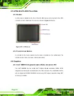
1.2.2 Rear Panel
The rear panel provides access to retention screw holes that support the wall mounting.
Refer to
.
Figure 1-3: AFL-9652 Rear View
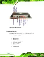
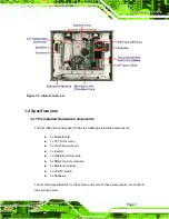
1.2.3 Bottom Panel
The bottom panel of the AFL-9652 series has the following I/O interfaces (
1 x 12 V DC power input connector
1 x Audio jack
1 x AT/ATX switch
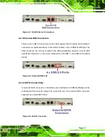
1 x eSATA port
1 x Power switch
1 x Reset button
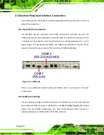
1 x RS-232 serial port connector
1 x RS-232/422/485 serial port connector
2 x RJ-45 10/100/1000Mbps Ethernet connectors
4 x USB 2.0 connectors
1 x VGA port
Содержание AFL-15C-9652
Страница 18: ......
Страница 19: ...Page 1 1 Introduction Chapter 1...
Страница 28: ...Page 10 2 Specifications Chapter 2...
Страница 42: ...Page 24 3 Unpacking Chapter 3...
Страница 46: ...Page 28 4 Installation Chapter 4...
Страница 68: ...Page 50 5 System Maintenance Chapter 5...
Страница 76: ...Page 58 6 AMI BIOS Setup Chapter 6...
Страница 123: ...Page 105 Chapter 7 7 Software Drivers...
Страница 168: ...Page 150 8 Intel AMT Configuration Chapter 8...
Страница 178: ...Page 160 A System Specifications Appendix A...
Страница 184: ...Page 166 B Safety Precautions Appendix B...
Страница 188: ...Page 170 C BIOS Configuration Options Appendix C...
Страница 193: ...Page 175 D Watchdog Timer Appendix D...
Страница 196: ...Page 178 E Hazardous Materials Disclosure Appendix E...


