


AFL-057A-Z510/Z530 Panel PC
Page 41
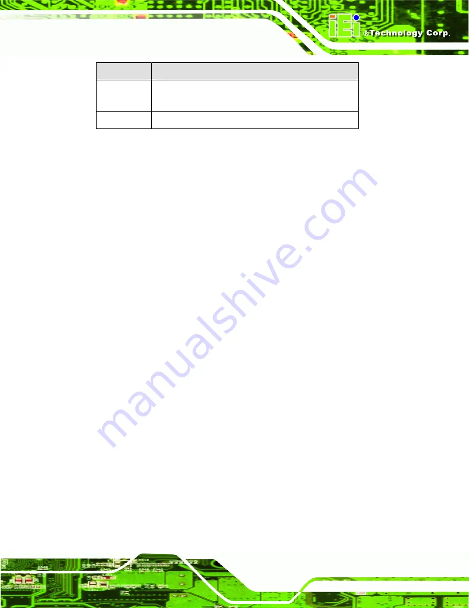
Key
Function
F2 /F3 key
Change color from total three colors. F2 to select color
forward.
F10 key
Save all the CMOS changes, only for Main Menu
Table 5-1: BIOS Navigation Keys
5.1.3 Getting Help
When
F1
is pressed a small help window describing the appropriate keys to use and the
possible selections for the highlighted item appears. To exit the Help Window press
E
SC
or
the
F1
key again.
5.1.4 Unable to Reboot After Configuration Changes
If the computer cannot boot after changes to the system configuration are made, CMOS
defaults. Use the jumper described in
Chapter
5
.
5.1.5 BIOS Menu Bar
The
menu bar
on top of the BIOS screen has the following main items:
Main – Changes the basic system configuration.
Advanced – Changes the advanced system settings.
PCIPnP – Changes the advanced PCI/PnP Settings
Boot – Changes the system boot configuration.
Security – Sets User and Supervisor Passwords.
Chipset – Changes the chipset settings.
Exit – Selects exit options and loads default settings
The following sections completely describe the configuration options found in the menu
items at the top of the BIOS screen and listed above.
Содержание AFL-057A-Z510
Страница 12: ...AFL 057A Z510 Z530 Panel PC Page 1 Chapter 1 1 Introduction ...
Страница 20: ...AFL 057A Z510 Z530 Panel PC Page 9 Chapter 2 2 Packing List ...
Страница 25: ...AFL 057A Z510 Z530 Panel PC Page 14 Chapter 3 3 Installation ...
Страница 46: ...AFL 057A Z510 Z530 Panel PC Page 35 Chapter 4 4 System Maintenance ...
Страница 49: ...AFL 057A Z510 Z530 Panel PC Page 38 Figure 4 2 DDR2 SO DIMM Module Installation ...
Страница 50: ...AFL 057A Z510 Z530 Panel PC Page 39 Chapter 5 5 BIOS ...
Страница 76: ...AFL 057A Z510 Z530 Panel PC Page 65 Appendix A A Safety Precautions ...
Страница 81: ...AFL 057A Z510 Z530 Panel PC Page 70 Appendix B B BIOS Options ...
Страница 84: ...AFL 057A Z510 Z530 Panel PC Page 73 Appendix C C One Key Recovery ...
Страница 112: ...AFL 057A Z510 Z530 Panel PC Page 101 Appendix D D Terminology ...
Страница 116: ...AFL 057A Z510 Z530 Panel PC Page 105 Appendix E E Watchdog Timer ...
Страница 119: ...AFL 057A Z510 Z530 Panel PC Page 108 Appendix F F Hazardous Materials Disclosure ...


