AFL-057A-Z510/Z530 Panel PC
Page 28
Step 3:
Secure the connector
. Secure the serial device connector to the external
interface by tightening the two retention screws on either side of the connector.
3.6.3 USB Device Connection
There is one external USB 2.0 connector. To connect a USB 2.0 or USB 1.1 device,
please follow the instructions below.
Step 1:
Located the USB connectors
. The location of the USB connector is shown in
Chapter 2
.
Step 2:
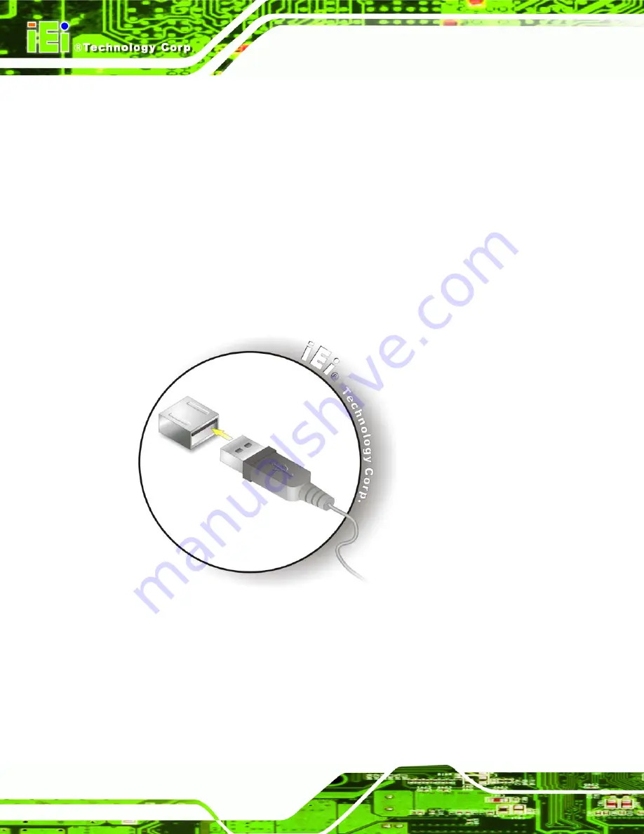
Align the connectors.
Align the USB device connector with one of the
connectors on the bottom panel. See
Figure 3-12: USB Device Connection
Step 3:
Insert the device connector.
Once aligned, gently insert the USB device
connector into the onboard connector.
Содержание AFL-057A-Z510
Страница 12: ...AFL 057A Z510 Z530 Panel PC Page 1 Chapter 1 1 Introduction ...
Страница 20: ...AFL 057A Z510 Z530 Panel PC Page 9 Chapter 2 2 Packing List ...
Страница 25: ...AFL 057A Z510 Z530 Panel PC Page 14 Chapter 3 3 Installation ...
Страница 46: ...AFL 057A Z510 Z530 Panel PC Page 35 Chapter 4 4 System Maintenance ...
Страница 49: ...AFL 057A Z510 Z530 Panel PC Page 38 Figure 4 2 DDR2 SO DIMM Module Installation ...
Страница 50: ...AFL 057A Z510 Z530 Panel PC Page 39 Chapter 5 5 BIOS ...
Страница 76: ...AFL 057A Z510 Z530 Panel PC Page 65 Appendix A A Safety Precautions ...
Страница 81: ...AFL 057A Z510 Z530 Panel PC Page 70 Appendix B B BIOS Options ...
Страница 84: ...AFL 057A Z510 Z530 Panel PC Page 73 Appendix C C One Key Recovery ...
Страница 112: ...AFL 057A Z510 Z530 Panel PC Page 101 Appendix D D Terminology ...
Страница 116: ...AFL 057A Z510 Z530 Panel PC Page 105 Appendix E E Watchdog Timer ...
Страница 119: ...AFL 057A Z510 Z530 Panel PC Page 108 Appendix F F Hazardous Materials Disclosure ...


