IEI Technology ACT-412A-N270 Скачать руководство пользователя страница 90


ACT-412A-N270 User Manual

Page 90 

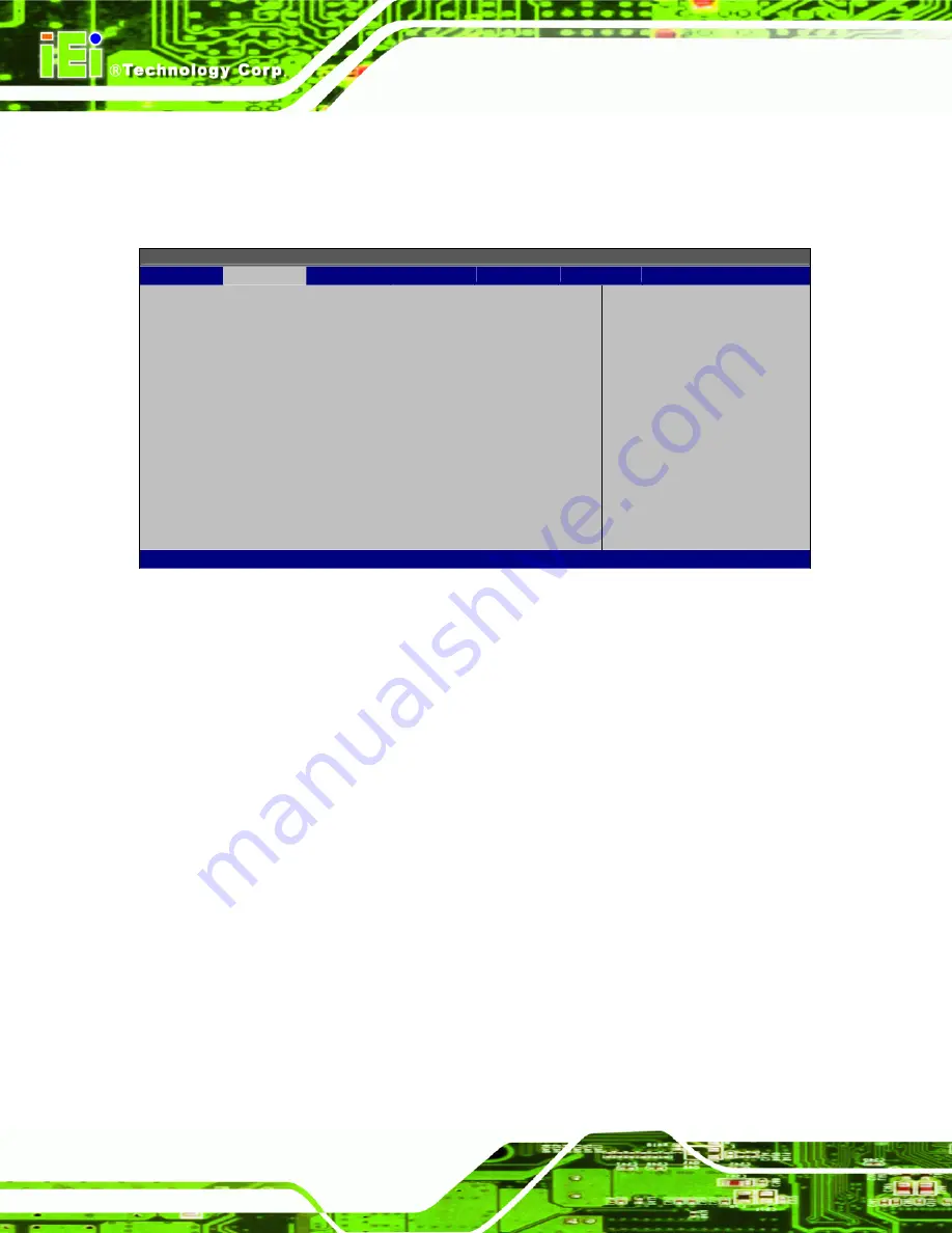
5.3.6 ACPI Configuration 

Use the 

ACPI Configuration

 menu (

BIOS Menu 9

) to select the ACPI state when the 

system is suspended. 

BIOS SETUP UTILITY 

Main 

Advanced 

PCIPNP 

Boot 

Security

Chipset

Power 

Exit 

 
General ACPI Configuration 

⎯⎯⎯⎯⎯⎯⎯⎯⎯⎯⎯⎯⎯⎯⎯⎯⎯⎯⎯⎯⎯⎯⎯⎯⎯⎯⎯⎯⎯⎯⎯


Suspend Mode 

[S1 (POS)] 


 Select 

Screen 


 Select 

Item 

Enter Go to SubScreen 
F1 General 

Help 

F10 

Save and Exit 

ESC Exit 

v02.61 ©Copyright 1985-2006, American Megatrends, Inc. 

BIOS Menu 9: General ACPI Configuration


Suspend Mode [S1(POS)] 

Use the 

Suspend Mode

 option to specify the sleep state the system enters when it is not 

being used. 


S1 (POS)  D

EFAULT


The system enters S1(POS) sleep state. The system 

appears off. The CPU is stopped; RAM is refreshed; the 

system is running in a low power mode. 


S3 (STR) 


System appears off. The CPU has no power; RAM is in 

slow refresh; the power supply is in a reduced power 

mode. 


Содержание ACT-412A-N270

Страница 1: ...Page i IEI Technology Corp User Manual MODEL ACT 412A N270 Panel PC with Touch Screen and 1 6 GHz Intel Atom CPU Gigabit Ethernet 3 USB Audio RS 232 422 485 eSATA SATA RoHS Compliant IP 64 Protection...

Страница 2: ...ACT 412A N270 User Manual Page ii Revision Date Version Changes 3 September 2010 1 20 LCD panel update 30 September 2009 1 00 Initial release...

Страница 3: ...es arising out of the use or inability to use the product or documentation even if advised of the possibility of such damages This document contains proprietary information protected by copyright All...

Страница 4: ...VERVIEW 18 1 4 SPECIFICATIONS 18 1 4 1 System Specifications 18 1 5 DIMENSIONS 20 2 INSTALLATION 22 2 1 UNPACKING 23 2 1 1 Packing List 23 2 2 ANTI STATIC PRECAUTIONS 25 2 3 INSTALLATION PRECAUTIONS 2...

Страница 5: ...Mounting 43 2 11 3 Arm Mounting 46 2 12 BOTTOM PANEL CONNECTORS 47 2 12 1 LAN Connection 47 2 12 2 Serial Device Connection 48 2 12 3 USB Device Connection 49 3 RFID READER 51 3 1 INTRODUCTION 52 3 2...

Страница 6: ...PU Configuration 77 5 3 2 IDE Configuration 78 5 3 2 1 IDE Master IDE Slave 79 5 3 3 Super I O Configuration 84 5 3 4 Hardware Health Configuration 86 5 3 5 Power Configuration 89 5 3 6 ACPI Configura...

Страница 7: ...L PORT CONNECTOR COM3 118 A 8 USB CONNECTORS 118 B SAFETY PRECAUTIONS 119 B 1 SAFETY PRECAUTIONS 120 B 1 1 Anti static Precautions 121 B 2 MAINTENANCE AND CLEANING PRECAUTIONS 121 B 2 1 Cleaning Tools...

Страница 8: ...MOS Jumper 34 Figure 2 7 COM1 and COM3 Pin 9 Setting Jumper Locations 35 Figure 2 8 COM3 RX Function Select Jumper Location 37 Figure 2 9 COM3 TX Function Select Jumper Pinout Locations 38 Figure 2 10...

Страница 9: ...n 53 Figure 3 4 Current Settings Confirmation Screen 54 Figure 3 5 RF320 COM Port Settings 56 Figure 3 6 Read Block 58 Figure 3 7 Write Block 59 Figure 3 8 Set Mifare Parameter 61 Figure 3 9 Get Mifar...

Страница 10: ...ion Select Jumper Settings 37 Table 2 10 COM3 RS 232 422 485 Serial Port Select Jumper Settings 39 Table 3 1 RF320 COM Port Settings 56 Table 3 2 Read Block Raw Data Format 58 Table 3 3 Read Block Res...

Страница 11: ...nfiguration 90 BIOS Menu 10 APM Configuration 91 BIOS Menu 11 Remote Access Configuration 93 BIOS Menu 12 USB Configuration 97 BIOS Menu 13 PCI PnP Configuration 99 BIOS Menu 14 Boot 101 BIOS Menu 15...

Страница 12: ...ACT 412A N270 User Manual Page 12 Chapter 1 1 Introduction...

Страница 13: ...ed with an Intel ICH7M input output controller hub ensures optimal memory graphics and peripheral I O support The system comes with 1 GB of preinstalled DDR2 SDRAM and supports a maximum of 2 0 GB of...

Страница 14: ...ccess Time attendance Cashless payment terminal Parking access control 1 2 External Overview The stylish ACT 412A N270 access control terminal comprises of a screen front and rear panels An ABS PC pla...

Страница 15: ...ACT 412A N270 User Manual Page 15 Figure 1 2 ACT 412A N270 Front View Figure 1 3 Front View Faceplate Removed...

Страница 16: ...Mifare tags or EM tags Please refer to Chapter 5 for detailed description of the RFID tool RF320 1 2 3 Rear Panel The rear panel provides access to retention screw holes that support the VESA 75 and 1...

Страница 17: ...RS 422 485 port 2 x RJ 45 GbE LAN connectors 2 x USB 2 0 ports 1 x Reset button The external I O interface connectors on the rear panel are shown in Figure 1 5 Figure 1 5 ACT 412A N270 Bottom View 1 2...

Страница 18: ...lled components 1 x Motherboard 1 x TFT LCD screen 1 x Touch screen 1 x Inverter 1 x Wireless LAN module 1 x DDR2 memory module 1 x AT ATX switch The following section lists the system specifications...

Страница 19: ...255 sec system reset Audio ALC888 HD Audio codec AMP 2 0 W AMP 2 0 W built in stereo speakers Expansion One PCIe Mini card slot for wireless LAN 802 11 b g module Camera and MIC Built in 300 K pixel...

Страница 20: ...e 6 pin terminal block for signal input 2 x Digital Input 2 x Digital Output One eSATA port One Audio line out jack One RS 232 COM port One RS 232 422 485 COM port Two RJ 45 GbE LAN connectors Three U...

Страница 21: ...ACT 412A N270 User Manual Page 21 Figure 1 7 ACT 412A N270 Dimensions mm...

Страница 22: ...ACT 412A N270 User Manual Page 22 Chapter 2 2 Installation...

Страница 23: ...s a knife or a sharp pair of scissors that seals the top side of the external second box Step 2 Open the external second box Step 3 Use box cutters a knife or a sharp pair of scissors that seals the t...

Страница 24: ...ntrol terminal 1 Screw set 4 Adhesive foam tape strips 1 Power adapter 1 Power cord 1 Touch pen 1 User manual CD and driver CD 1 External SATA cable 1 Mini jumper pack 2 0 mm If any of these items are...

Страница 25: ...ing the board Self grounding Before handling the board touch any grounded conducting material During the time the board is handled frequently touch any conducting materials that are connected to the g...

Страница 26: ...5 Installation and Configuration Steps The following installation steps must be followed Step 1 Unpack the ACT 412A N270 Step 2 Install SATA HDD Step 3 Install CF card Step 4 Configure the system Step...

Страница 27: ...2 7 Hard Drive Installation Step 3 The ACT 412A N270 has one hard drive bay inside the rear panel To install a hard drive follow the instructions below Step 4 Locate the HDD bracket and insert the HD...

Страница 28: ...2A N270 has one CF Type II slot To install the CF card follow the instructions below Step 1 Locate the CF card slot cover The CF card slot cover is located on the back panel of the ACT 412A N270 See F...

Страница 29: ...t and insert the CF card into the socket See Figure 2 4 Figure 2 4 CF Card Installation Step 4 Replace the CF card slot cover Make sure the cover is properly secured with the previously removed retent...

Страница 30: ...Point of Sale POS Advertising terminal 2 9 1 2 AT Power Mode With the AT mode selected the power is controlled by a central power unit rather than a power switch The ACT 412A N270 panel PC turns on au...

Страница 31: ...CT 412A N270 is installed the jumpers must be set in accordance with the desired configuration The jumpers on the ACT 412A N270 motherboard are listed in Table 2 1 Description Label Type Clear CMOS J_...

Страница 32: ...tention Screws 2 10 2 Preconfigured Jumpers WARNING Do not change the settings on the jumpers in described here Doing so may disable or damage the system The following jumpers are preconfigured for th...

Страница 33: ...the jumper clip If the CMOS Settings Wrong message is displayed during the boot up process the fault may be corrected by pressing the F1 to enter the CMOS Setup menu Do one of the following Enter the...

Страница 34: ...JP10 configure pin 9 on COM1 and COM3 DB 9 connectors Pin 9 on the COM1 and the COM3 DB 9 connectors can be set as the ring RI signal 5 V or 12 V The COM1 and COM3 Pin 9 Setting jumper selection optio...

Страница 35: ...ing Jumper Settings The COM1 and COM3 Pin 9 Setting jumper locations are shown in Figure 2 7 below Figure 2 7 COM1 and COM3 Pin 9 Setting Jumper Locations 2 10 4 1 COM3 RS 422 and RS 485 Pinouts The p...

Страница 36: ...igure 2 8 The COM3 RX Function Select jumper sets the communication protocol used by the RX serial communications port COM3 as RS 232 RS 422 or RS 485 The COM3 RX Function Select jumper settings are s...

Страница 37: ...ee Table 2 9 Jumper Location See Figure 2 9 The COM3 TX Function Select jumper configures the TX pin on COM3 serial port connector as RS 422 as an RS 485 The COM3 TX Function Select jumper selection o...

Страница 38: ...erial Port Select Jumper Jumper Label JP6 Jumper Type 12 pin header four 3 pin headers combined Jumper Settings See Table 2 10 Jumper Location See Figure 2 10 The COM3 RS 232 422 485 Serial Port Selec...

Страница 39: ...422 485 Serial Port Select Jumper Settings The COM3 RS 232 422 485 Serial Port Select jumper location is shown in Figure 2 10 Figure 2 10 COM3 RS 232 422 485 Serial Port Select Jumper Location 2 10 8...

Страница 40: ...Adjust the AT ATX switch The default mode is ATX mode Figure 2 11 Step 3 2 11 Mounting the System WARNING When mounting the flat panel PC onto an arm onto the wall or into a wall it is better to have...

Страница 41: ...bracket screw holes with the pilot holes Step 8 Secure the mounting bracket to the wall by inserting the retention screws into the four pilot holes and tightening them Figure 2 12 Figure 2 12 Wall mou...

Страница 42: ...3 Ensure that all four of the mounting screws fit snuggly into their respective slotted holes Figure 2 13 Chassis Support Screws NOTE In the diagram below the bracket is already installed on the wall...

Страница 43: ...12A N270 2 11 2 In wall Mounting Before installing into a wall mounting attach the adhesive strips to the sides as shown below Step 13 Place the ACT 412A N270 face down on a flat surface Figure 2 15 C...

Страница 44: ...ver the screw holes as shown below Step 15 Figure 2 17 Foam Tape Installed To mount the ACT 412A N270 panel PC into a wall please follow the steps below Step 16 Select the position on the wall to moun...

Страница 45: ...ole until the frame is flush against the wall Step 19 Tighten the screws that pass through the wall mounting screw holes until the screws are firmly secured to the wall Figure 2 19 Figure 2 19 Tighten...

Страница 46: ...se To do this refer to the installation documentation that came with the mounting arm NOTE When purchasing the arm please ensure that it is VESA compliant and that the arm has a 75 mm or 100 mm interf...

Страница 47: ...Bottom Panel Connectors 2 12 1 LAN Connection There are two external RJ 45 LAN connectors The RJ 45 connectors enable connection to an external network To connect a LAN cable with an RJ 45 connector...

Страница 48: ...onnection The ACT 412A N270 has two male DB 9 connectors on the bottom panel for serial devices to be connected Follow the steps below to connect a serial device to the ACT 412A N270 POS system Step 1...

Страница 49: ...or Step 0 2 12 3 USB Device Connection There are four external USB 2 0 connectors All connectors are perpendicular to the ACT 412A N270 To connect a USB 2 0 or USB 1 1 device please follow the instruc...

Страница 50: ...ACT 412A N270 User Manual Page 50 Figure 2 24 USB Device Connection Step 3 Insert the device connector Once aligned gently insert the USB device connector into the onboard connector Step 0...

Страница 51: ...ACT 412A N270 User Manual Page 51 Chapter 3 3 RFID Reader...

Страница 52: ...rds To install the RF320 please follow the steps below The following example is based on the Windows XP environment Step 1 Run the RF 320 setup V1 3 2 exe file from the utility CD Step 2 The InstallSh...

Страница 53: ...is stage in Figure 3 3 appears Please choose the setup type Click NEXT to continue the installation Figure 3 3 Setup Type Selection Screen Step 6 The window shows the current settings for installing t...

Страница 54: ...ACT 412A N270 User Manual Page 54 Figure 3 4 Current Settings Confirmation Screen Step 7 Click FINISH to exit Step 8 To launch the RF320 click Start menu Program File IEI RF320 Step 0...

Страница 55: ...elect Data Input Area The data input area is where the user enters block number key key data and other information required by certain commands Raw Data Display Area Shows all communication logs and r...

Страница 56: ...to enable the communication with the built in RFID reader Please follow the information below to setup the COM port settings Model COM Port Baud Rate ACT 412A N270 COM 2 19200 Table 3 1 RF320 COM Port...

Страница 57: ...Set RF320 Mode The following sections describe how to use these commands 3 5 1 Read Block To read the block data from a Mifare card please follow the steps below Step 1 Select Read Block in the comma...

Страница 58: ...e Out End Digit 2 2 1 12 2 1 Data RB 00 63 A B 000000000000 Hex FFFFFFFFFFFF 00 99 Second CR 0x0d Table 3 2 Read Block Raw Data Format Status 2 digits Block Data 32 digits END 2 digits OK 32 bits Hex...

Страница 59: ...command area Figure 3 7 Step 5 Configure the data including block key key data time out and data Figure 3 7 Step 6 Click the Execute button to execute the command through the selected serial port Figu...

Страница 60: ...t parameter of a Mifare card reader please follow the steps below Step 7 Select Set Mifare Parameter in the command area Figure 3 8 Step 8 Select a Mifare mode 0 UUID read serial number only 1 UUID KE...

Страница 61: ...CR 0x0d Table 3 6 Set Mifare Parameter Raw Data Format Status 2 digits Block Data END 2 digits OK Null CR LF 0x0d 0x0a ER Error Code 3 digits CR LF 0x0d 0x0a Table 3 7 Set Mifare Parameter Response F...

Страница 62: ...mat listed in Table 3 8 and Table 3 9 Step 12 Figure 3 9 Get Mifare Parameter Field Command End Digit 2 1 Data RM CR 0x0d Table 3 8 Get Mifare Parameter Raw Data Format Status 2 digits Block Data END...

Страница 63: ...in the command area Figure 3 10 Step 14 Select a RF320 mode 1 EM12K detect EM cards only 2 Mifare detect Mifare cards only 3 EM and Mifare detect both EM and Mifare cards Step 15 Click the Execute but...

Страница 64: ...d Command Mode End Digit 2 1 1 Data SA 1 3 CR 0x0d Table 3 10 Set RF320 Mode Raw Data Format Status 2 digits Block Data END 2 digits OK Null CR LF 0x0d 0x0a ER Error Code 3 digits CR LF 0x0d 0x0a Tabl...

Страница 65: ...ACT 412A N270 User Manual Page 65 Chapter 4 4 System Maintenance...

Страница 66: ...trostatic discharge ESD can cause serious damage to electronic components including the ACT 412A N270 Dry climates are especially susceptible to ESD It is therefore critical that whenever the ACT 412A...

Страница 67: ...e carried out on the system make sure the system is turned off 4 4 Removing the Rear Panel To access the ACT 412A N270 internally the rear panel must be removed To remove the rear panel please follow...

Страница 68: ...4 5 1 CF Card Replacement The ACT 412A N270 has one CF Type II slot To replace the CF card follow the instructions below Step 1 Follow all anti static procedures See Section 4 2 Step 2 Turn off the po...

Страница 69: ...s See Section 4 2 Step 5 Turn off the power See Section 4 3 Step 6 Remove the back panel See Section 4 4 Step 7 Locate the SO DIMM module See Figure 4 2 Figure 4 2 SO DIMM Socket Location Step 8 Open...

Страница 70: ...tep 0 4 5 3 Wireless Module Replacement To replace the wireless module please follow the steps below Step 1 Follow all anti static procedures See Section 4 2 Step 2 Turn off the power See Section 4 3...

Страница 71: ...with the Mini PCIe card socket The wireless module must be oriented in such a way that the notch in the wireless module must be aligned with the plastic bridge in the socket Step 8 Insert the wireless...

Страница 72: ...ACT 412A N270 User Manual Page 72 Chapter 5 5 BIOS...

Страница 73: ...e disappears before the DELETE key is pressed restart the computer and try again 5 1 2 Using Setup Use the arrow keys to highlight items press ENTER to select use the PageUp and PageDown keys to chang...

Страница 74: ...ges to the system configuration is made CMOS defaults Use the jumper described in Chapter 5 5 1 5 BIOS Menu Bar The menu bar on top of the BIOS screen has the following main items Main Changes the bas...

Страница 75: ...creen Select Item Enter Go to SubScreen F1 General Help F10 Save and Exit ESC Exit v02 61 Copyright 1985 2006 American Megatrends Inc BIOS Menu 1 Main System Overview The System Overview lists a brief...

Страница 76: ...enu BIOS Menu 2 to configure the CPU and peripheral devices BIOS SETUP UTILITY Main Advanced PCIPNP Boot Security Chipset Exit Advanced Settings WARNING Setting wrong values in below sections may caus...

Страница 77: ...B Speed 532MHz Cache L1 24KB Cache L2 512KB Ratio Actual Value 12 Select Screen Select Item Enter Go to SubScreen F1 General Help F10 Save and Exit ESC Exit v02 61 Copyright 1985 2006 American Megatre...

Страница 78: ...nhanced Select Screen Select Item Enter Go to SubScreen F1 General Help F10 Save and Exit ESC Exit v02 61 Copyright 1985 2006 American Megatrends Inc BIOS Menu 4 IDE Configuration ATA IDE Configuratio...

Страница 79: ...R T Auto 32Bit Data Transfer Enabled Select the type of device connected to the system Select Screen Select Item Change Option F1 General Help F10 Save and Exit ESC Exit v02 61 Copyright 1985 2006 Am...

Страница 80: ...ted 32Bit Data Transfer Enables 32 bit data transfer Type Auto Use the Type BIOS option select the type of device the AMIBIOS attempts to boot from after the Power On Self Test POST is complete Not In...

Страница 81: ...g Multi Sector Transfer on the specified channel The data to and from the device occurs one sector at a time Auto DEFAULT BIOS auto detects Multi Sector Transfer support on the drive on the specified...

Страница 82: ...ord DMA mode 0 selected with a maximum data transfer rate of 2 1 MB s SWDMA1 Single Word DMA mode 1 selected with a maximum data transfer rate of 4 2 MB s SWDMA2 Single Word DMA mode 2 selected with a...

Страница 83: ...M A R T Auto Use the S M A R T option to auto detect disable or enable Self Monitoring Analysis and Reporting Technology SMART on the drive on the specified channel S M A R T predicts impending drive...

Страница 84: ...85 RS232 Serial Port4 Address 2E8 Serial Port4 IRQ 10 Allows BIOS to select Serial Port1 Base Addresses Select Screen Select Item Enter Go to SubScreen F1 General Help F10 Save and Exit ESC Exit V02 6...

Страница 85: ...ss 11 Serial Port4 Address 2E8 Selects the serial port base address Disabled No base address 3E8 I O address 3E8 2E8 DEFAULT I O address 2E8 2F0 I O address 2F0 2E0 I O address 2E0 Serial Port4 IRQ 10...

Страница 86: ...ages BIOS SETUP UTILITY Main Advanced PCIPNP Boot Security Chipset Exit Hardware Health Event Monitoring CPU FAN Mode Setting Full On mode CPU Temperature 57 C 132 F System Temperature 47 C 116 F CPU...

Страница 87: ...PWM Slope PWM 1 PWM Manual mode The fan spins at the speed set in Fan PWM control Temp Limit of OFF 000 WARNING CPU failure can result if this value is set too high The fan will turn off if the temper...

Страница 88: ...imum Mode 0 PWM Maximum Mode 127 Slope PWM 1 PWM A greater value will increase the fan speed in large amounts A smaller value will increase the speed more gradually 0 PWM 1 PWM 2 PWM 4 PWM 8 PWM 16 PW...

Страница 89: ...d power management options to be configured BIOS SETUP UTILITY Main Advanced PCIPNP Boot Security Chipset Exit ACPI Configuration APM Configuration Select Screen Select Item Enter Go to SubScreen F1 G...

Страница 90: ...en F1 General Help F10 Save and Exit ESC Exit v02 61 Copyright 1985 2006 American Megatrends Inc BIOS Menu 9 General ACPI Configuration Suspend Mode S1 POS Use the Suspend Mode option to specify the s...

Страница 91: ...Select Item Enter Go to SubScreen F1 General Help F10 Save and Exit ESC Exit v02 61 Copyright 1985 2006 American Megatrends Inc BIOS Menu 10 APM Configuration Power Button Mode On Off Use the Power B...

Страница 92: ...end or standby state That is the system will be roused by an incoming call on a modem Disabled DEFAULT Wake event not generated by an incoming call Enabled Wake event generated by an incoming call Res...

Страница 93: ...OS feature and allows a remote host running a terminal program to display and configure the BIOS settings BIOS SETUP UTILITY Main Advanced PCIPNP Boot Security Chipset Exit Configure Remote Access typ...

Страница 94: ...used for remote access COM1 DEFAULT System is remotely accessed through COM1 COM2 System is remotely accessed through COM2 NOTE Make sure the selected COM port is enabled through the Super I O configu...

Страница 95: ...e is set as the console redirection Redirection After BIOS POST Always Use the Redirection After BIOS POST option to specify when console redirection should occur Disabled The console is not redirecte...

Страница 96: ...oes not support all keys on the standard PC 101 key layout however The VT UTF8 convention makes available additional keys that are not provided by VT100 for the PC 101 keyboard Disabled DEFAULT Disabl...

Страница 97: ...d Options Disabled Enabled Select Screen Select Item Enter Go to SubScreen F1 General Help F10 Save and Exit ESC Exit V02 61 Copyright 1985 2006 American Megatrends Inc BIOS Menu 12 USB Configuration...

Страница 98: ...g system is fully booted with all USB drivers loaded When this option is enabled any attached USB mouse or USB keyboard can control the system even when there is no USB driver loaded onto the system D...

Страница 99: ...nel 5 Available DMA Channel 6 Available DMA Channel 7 Available Reserved Memory Size Disabled Available Specified IRQ is available to be use the PCI PnP devices Reserved Specified IRQ is reserved for...

Страница 100: ...I PnP device Available DEFAULT The specified DMA is available to be used by PCI PnP devices Reserved The specified DMA is reserved for use by Legacy ISA devices Available DMA Channels are DM Channel 0...

Страница 101: ...e the Boot menu BIOS Menu 14 to configure system boot options BIOS SETUP UTILITY Main Advanced PCIPNP Boot Security Chipset Exit Boot Settings Boot Settings Configuration Boot Device Priority Hard Dis...

Страница 102: ...ing This will decrease the time needed to boot the system Select Screen Select Item Enter Go to SubScreen F1 General Help F10 Save and Exit ESC Exit v02 61 Copyright 1985 2006 American Megatrends Inc...

Страница 103: ...keys on the keyboard press the Number Lock key located on the upper left hand corner of the 10 key pad The Number Lock LED on the keyboard lights up when the Number Lock is engaged On DEFAULT Allows...

Страница 104: ...om the available devices The drive sequence also depends on the boot sequence in the individual device section BIOS SETUP UTILITY Main Advanced PCIPNP Boot Security Chipset Exit Boot Device Priority 1...

Страница 105: ...OS SETUP UTILITY Main Advanced PCIPNP Boot Security Chipset Exit Hard Disk Drives 1st Drive Hard Drive 1 2nd Drive Hard Drive 2 3rd Drive Hard Drive 3 Specifies the boot sequence from the available de...

Страница 106: ...een Select Item Enter Go to SubScreen F1 General Help F10 Save and Exit ESC Exit v02 61 Copyright 1985 2006 American Megatrends Inc BIOS Menu 18 Removable Drives 5 5 5 CD DVD Drives Use the CD DVD Dri...

Страница 107: ...oot sequence from the available devices Select Screen Select Item Enter Go to SubScreen F1 General Help F10 Save and Exit ESC Exit v02 61 Copyright 1985 2006 American Megatrends Inc BIOS Menu 19 CD DV...

Страница 108: ...rvisor Password Change User Password Use the Change User Password to set or change a user password The default for this option is Not Installed If a user password must be installed select this field a...

Страница 109: ...iguration menu BIOS Menu 22 to configure the Northbridge chipset BIOS SETUP UTILITY Main Advanced PCIPNP Boot Security Chipset Exit Northbridge Configuration Memory Hole Disabled Internal Graphics Mod...

Страница 110: ...phic Mode Select option to specify the amount of system memory that can be used by the Internal graphics device Disable Disabled the onboard graphics Enable 1 MB Dedicates 1 MB of main memory for grap...

Страница 111: ...maximum amount of graphics memory is 128 MB Configuration options are listed below 64 MB 128 MB DEFAULT Maximum DVMT Boot Display Device Auto Selects which graphics output to use first after the syst...

Страница 112: ...is selected in the setting above 5 7 2 Southbridge Configuration The Southbridge Configuration menu BIOS Menu 23 configures the Southbridge chipset BIOS SETUP UTILITY Main Advanced PCIPNP Boot Securit...

Страница 113: ...t Options Save Changes and Exit Discard Changes and Exit Discard Changes Load Optimal Defaults Load Failsafe Defaults Exit system setup after saving the changes F10 key can be used for this operation...

Страница 114: ...Load Optimal Defaults Use the Load Optimal Defaults option to load the optimal default values for each of the parameters on the Setup menus F9 key can be used for this operation Load Failsafe Default...

Страница 115: ...ACT 412A N270 User Manual Page 115 Appendix A A External Connector Pinouts...

Страница 116: ...ctor The Digital I O connector on the bottom panel has the following pinouts PIN NO DESCRIPTION 1 VCC 2 GND 3 DO0 4 DO1 5 DI0 6 DI1 Digital I O Connector Pinouts A 3 External SATA Connector The ACT 41...

Страница 117: ...NO DESCRIPTION PIN NO DESCRIPTION 1 X1 2 X1 3 X2 4 X2 5 VCC2_5 6 GND 7 X3 8 X3 9 X4 10 X4 11 X1 12 ACT 1 13 LINK1000 LED 14 LINK100 LED LAN Connector Pinouts A 5 Power Connector The power jack on the...

Страница 118: ...1 5 GND COM1 Pinouts A 7 Serial Port Connector COM3 The ACT 412A N270 has a DB 9 female connector for RS 232 422 485 devices PIN NO DESCRIPTION PIN NO DESCRIPTION 1 DCD3 TX3 D 6 DSR3 RX1 2 RX3 TX3 D 7...

Страница 119: ...ACT 412A N270 User Manual Page 119 Appendix B B Safety Precautions...

Страница 120: ...modified Do not apply voltage levels that exceed the specified voltage range Doing so may cause fire and or an electrical shock Electric shocks can occur if the ACT 412A N270 chassis is opened when th...

Страница 121: ...ouch any grounded conducting material During the time the electrical component is handled frequently touch any conducting materials that are connected to the ground Use an anti static pad When configu...

Страница 122: ...e ACT 412A N270 Cloth Although paper towels or tissues can be used a soft clean piece of cloth is recommended when cleaning the ACT 412A N270 Water or rubbing alcohol A cloth moistened with water or r...

Страница 123: ...ACT 412A N270 User Manual Page 123 Appendix C C BIOS Configuration Options...

Страница 124: ...r Auto 81 PIO Mode Auto 81 DMA Mode Auto 82 S M A R T Auto 83 32Bit Data Transfer Enabled 83 Serial Port1 Address 3F8 IRQ4 84 Serial Port3 Address 3E8 84 Serial Port3 IRQ 11 85 Serial Port4 Address 2E...

Страница 125: ...97 USB Function Enabled 97 USB 2 0 Controller Enabled 98 Legacy USB Support Enabled 98 USB2 0 Controller Mode HiSpeed 98 IRQ Available 99 DMA Channel Available 100 Reserved Memory Size Disabled 100 Q...

Страница 126: ...Page 126 Sec Display Device CRT 112 LFP Current Jumper Setting 112 Audio Controller Enabled 112 Save Changes and Exit 113 Discard Changes and Exit 113 Discard Changes 114 Load Optimal Defaults 114 Lo...

Страница 127: ...ACT 412A N270 User Manual Page 127 Appendix D D Watchdog Timer...

Страница 128: ...BIOS function call INT 15H is used to control the Watchdog Timer INT 15H AH 6FH Sub function AL 2 Sets the Watchdog Timer s period BL Time out value Its unit second is dependent on the item Watchdog T...

Страница 129: ...e system resets Example program INITIAL TIMER PERIOD COUNTER W_LOOP MOV AX 6F02H setting the time out value MOV BX 05 time out value is 5 seconds INT 15H ADD THE APPLICATION PROGRAM HERE CMP EXIT_AP 1...

Страница 130: ...ACT 412A N270 User Manual Page 130 Appendix E E Hazardous Materials Disclosure...

Страница 131: ...e presences of small quantities of certain materials in the product and is applicable to China RoHS only A label will be placed on each product to indicate the estimated Environmentally Friendly Use P...

Страница 132: ...uit Board X O O O O X Metal Fasteners X O O O O O Cable Assembly X O O O O X Fan Assembly X O O O O X Power Supply Assemblies X O O O O X Battery O O O O O O O This toxic or hazardous substance is con...

Страница 133: ...ACT 412A N270 User Manual Page 133 RoHS RoHS Pb Hg Cd CR VI PBB PBDE X O O O O X X O O O O X X O O O O X X O O O O O X O O O O X X O O O O X X O O O O X O O O O O O O SJ T11363 2006 X SJ T11363 2006...

Отзывы: