background image

Instruction Manual

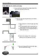
1   Remove the front grill, disconnect the terminals and then hide 

the terminals in the door’s reserved hole. 

2  Remove the right upper hinge and bottom door limit,then 

remove the door.

3  Take out the torsion rod from the upper right of the 

door.   

4  Fish out the wiring from door’s reserved hole, the 

wiring stretches out from the upper right of door.

5  Insert the torsion rod into corresponding holes on 

bottom right of the door.

6  Rotate the door clockwise 180°, so the wiring is 

stretching out from the bottom left of the door.

7  Remove the hinge axis from the right bottom hinge, 

inert it into the left bottom hinge.

DOOR REVERSAL (For G-10f Coolers Only)

11

reversible   door   exchange   

7.The   terminals   of   door   LED   lights   wiring   is   taken   out   from   

door's   reserved   hole then   get   through   hinge   axie    connect   


6.draw   out   the   hinge   axis   from   right   bottom   hinge,   insert   

it   into   left   bottom   hinge.

3.disassemble   the   right   upper   hinge,   then   remove   the   

door.

1.disassemble   the   the   hinge   latch   of   left   hand   door.

2.   disassemble   the   front   grill,   disconnect   the      terminals,   

then   hide   the   terminals   into   door's   reserved   hole.   

4.draw   out   the   structure   of   self-­‐closing   door,then   

assemble   the   structure   into   door   other   side      .      

5.clockwise   rotate   the   door   180°.

No.

change

Correction:
38 Electric Box Cover
47 Upper Compressor Baseboard

Delete clause 1 in the left and adjust the 
rest clause Seiral No and content as below:

1.Remove the front grill, disconnect the 
terminals and then hide the terminals in 
the door's reserved hole.
2.Remove upper hinge and bottom door 
limit,then remove the door.

remark: please add the above picture under 
the No1 picture.

5

G10F/12F manual modification

1

2

Cancel the 2 holes for LED light switches 
with labelling because the (2) LED light 
switched are moved to compressor room back

3.Take out the torsion rod from the upper  
of the door right
4.Fish out the wiring from door frame 
cavity, the wiring stretches out from the 
upper of door right.
5.Insert the torsion rod into corresponding 
holes on bottom right of the door.

6.Rotate the door clockwise 180°(Now the 

wiring is stretching out from the bottom  


Содержание G-10-F33EB

Страница 1: ...Series Cooler Instruction Manual G 10f GCG 10f UPRIGHT COOLER Manual is for the following models G 10F G 10 F33EB GCG 10F GCG 10 F33EB GCG 10F2 GCG 10 F233EB G 10 F33EB HC GCG 10 F33EB HC GCG 10 F233EB HC ...

Страница 2: ...Manual is for the following models G 10F G 10 F33EB GCG 10F GCG 10 F33EB GCG 10F2 GCG 10 F233EB G 10 F33EB HC GCG 10 F33EB HC GCG 10 F233EB HC G 10f GCG 10f Instruction Manual ...

Страница 3: ...ons 4 Features 5 Instructions 5 Flammable R290 Warnings 5 Ambient Environment 5 Preparation Before Operation 6 Replacing the Interior Light 7 Replacing the Door LED Lights 8 Setting Up Power Cord Holder 8 Startup Operation Temperature Adjustment 9 Lit Door Logo Switch 9 Repair Maintenance for Refrigeration Drawer 9 Condenser Maintenance 10 Maintenance 10 Cleaning Shutdown Questions Answers 10 Reve...

Страница 4: ...Instruction Manual 3 ...

Страница 5: ...ned for freestanding installation only 8 Do not operate or store your cooler near or around explosive fumes gasoline or other flammable vapors and liquids 9 Setting the temperature control to the 0 position does not remove power to the light circuit perimeter heaters or evaporator fans Please save these instructions DANGER Proper Disposal of the Refrigerator To prevent any risk of child entrapment ...

Страница 6: ... place cooler in below normal temperatures Do not place cooler in extreme humid environments this may cause components to rust Do not place cooler near constant running or splattering water this may cause immediate damage to refrigeration system Must allow at least 4 between rear of cooler and wall for proper ventilation and heat dissipation of cooler Do not place furniture or other articles with ...

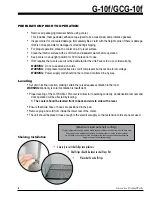
Страница 7: ... Leveling Set unit in its final location making certain there is adequate ventilation in the room WARNING Warranty is void if ventilation is insufficient Proper leveling of the G 10f GCG 10f cooler is critical to it operating correctly Condensation removal and door operation will be affected by leveling The cooler should be leveled front to back and side to side with a level Ensure that drain hose...

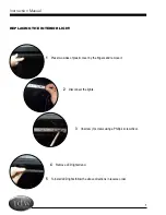
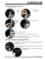
Страница 8: ...R LIGHT 1 Press two sides of plastic cover by the fingers and remove it 5 To install LED lights follow the above directions in reverse order 2 Disconnect the lights 4 Remove LED light strand 3 Unscrew 3 screws using a Phillip s screwdriver 7 ...

Страница 9: ... instructions in reverse order Notes If there are any malfunctions with the main control panel of LED lights please contact a professional for replacement SETTING UP SPACER POWER CORD HOLDERS The G 10f GCG 10f is supplied with one set 2 pieces of Spacers to hold the extra length of Power Cord 1 Take out the two Spacers and screws supplied in the Accessory Pack shipped with the Cooler 2 Use a Phill...

Страница 10: ...move the screws from the front grill and then remove the grill 3 Unplug all connections and terminals that are in need of repair 9 G 10f GCG 10f performance testing position of the thermostat is around 4 6 Component shown at the left functions as a secondary power source for low voltage items such as signs 4 Using a screwdriver remove the 3 screws from the refrigeration drawer base plate 5 Slide t...

Страница 11: ...is used shown left 5 Replace grill and utilize the Phillips screwdriver to tighten the screws into place replace the rubber caps MAINTENANCE Cleaning Shutdown Questions and Answers Cleaning and Maintenance 1 Unplug the cooler before cleaning 2 Use a soft cloth or sponge with water or soap non corrosive mild detergent while cleaning After cleaning wipe the cooler using dry cloth to keep the cooler ...

Страница 12: ...sert it into left bottom hinge 3 disassemble the right upper hinge then remove the door 1 disassemble the the hinge latch of left hand door 2 disassemble the front grill disconnect the terminals then hide the terminals into door s reserved hole 4 draw out the structure of self closing door then assemble the structure into door other side 5 clockwise rotate the door 180 Delete clause 1 in the left ...
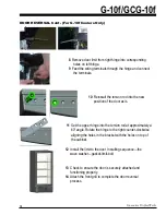
Страница 13: ...s reserved hole then get through hinge axie connect the terminals 10 assemble the front grill complete the reversible door exchange 9 fix the upper hinge into left axie sleeve then anticlockwise rotate the hinge to right position to fasten it 8 clockwise rotate the left axie sleeve 60 8 Remove door limit from right hinge into corresponding holes on left hinge 9 Feed the wiring terminals through th...

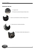
Страница 14: ... FUSE REPLACING THE FUSE 1 Unplug the cooler 2 Remove the screws from the back grill and then remove it 3 Open the cover of the fuse block as shown in the image to the left 4 Unscrew the fuse box then replace the bad fuse 5 After repair re install all parts reversing steps 1 5 ...

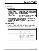
Страница 15: ...the door and lock assembly to avoid children accidentally becoming trapped inside the cooler AFTER SALES SERVICE Any product has the possibility of malfunction Please observe the cooler s operation and any changes to product being stored If there are any abnormal cases refer to the table below If there is still no change after following the below instructions please inform our service center in a ...

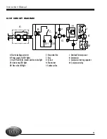
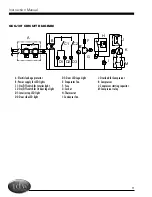
Страница 16: ...age protector B Power supply for LED lights C On Off switch for interior and door side light D1 Interior top LED light D2 Door side LED light E Evaporator Fan F Fuse G Socket H Thermostat I Condenser fan J Overload for compressor K Compressor L Compressor starting capacitor M Compressor relay ...

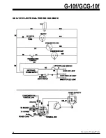
Страница 17: ...ATOR FAN BK RD WH WH BK BK TEMPERATURE CONTROL CONDENSER UNIT WH BK AC 125V 3A FUSE SOCKET SWITCHING POWER SUPPLY INTERIOR LIGHT SWITCH RD CONNECTIONS FOR EMI70UER COMPRESSOR POWER CORD GN WH WH BK RD BK WH L1 L2 N TERMINAL BOX TO HARNES GROUND WH RD START CAPACITY BK S R 2 1 RELAY C 1 WH 3 2 CONDENSER FAN CONTROL UNIT TO SOCKET GN WH BK ...

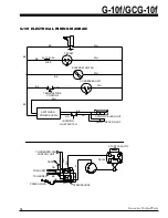
Страница 18: ...fan F Fuse G Socket H Thermostat I Condenser fan A Electric leakage protector B Power supply for LED lights C1 On Off switch for Interior light C2 On Off switch for lit door logo light D1 Interior top LED light D2 Door side LED light J Overload for Compressor K Compressor L Conpressor starting capacitor M Compressor relay ...

Страница 19: ...Innovative DisplayWorks G 10f GCG 10f 18 GCG 10f ELECTRICAL WIRING DIAGRAM ...

Страница 20: ...Innovative DisplayWorks Inc To locate the distributor in your area go to http www idw global contact distributors ...

Отзывы: