08/23/15
7
P9038 LAYOUT GUIDE
AN-894
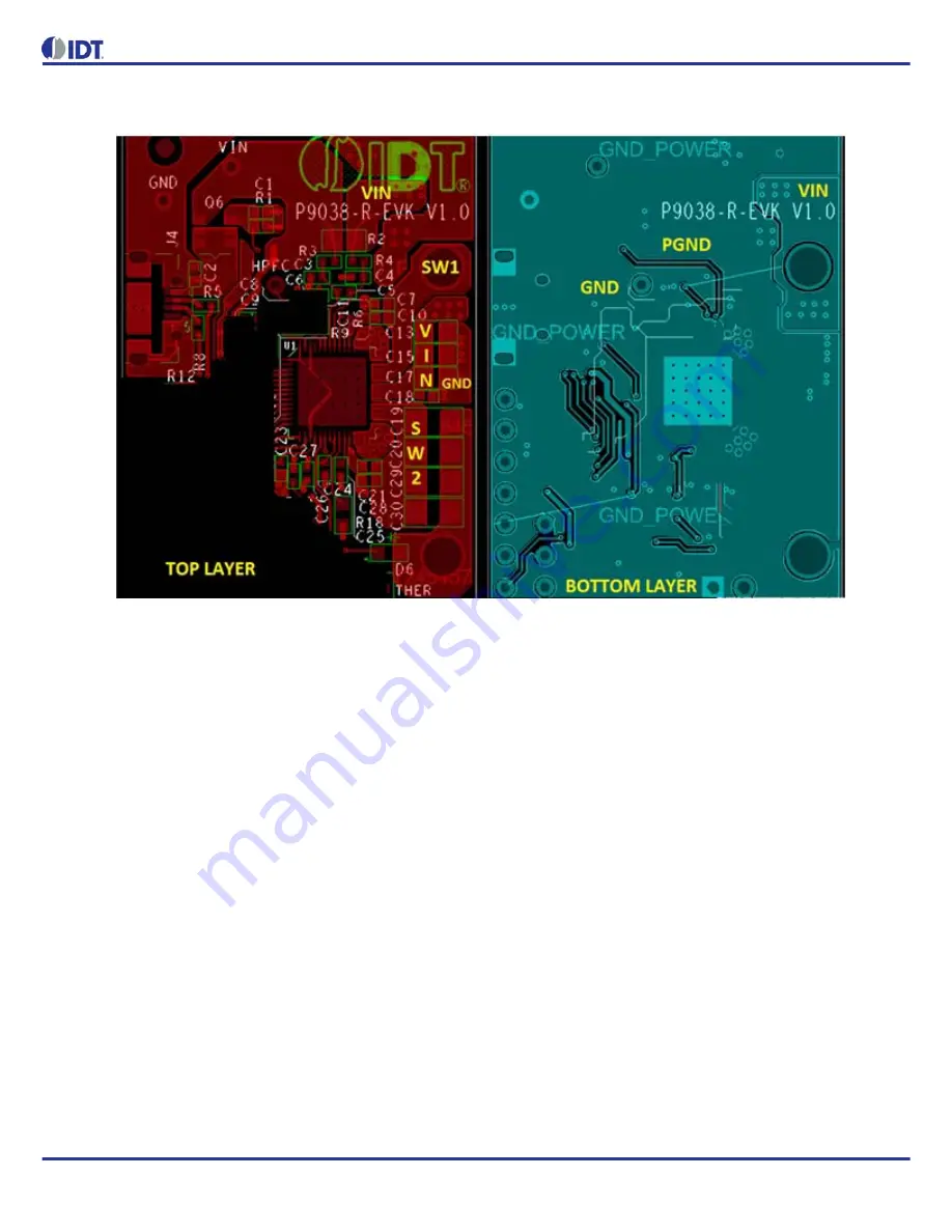
Figure 5. P9038 2-Layer Layout Main Input Power Example for Routing VIN on Top Layer to Input Capacitors
Input Capacitors
The input capacitors are labeled C13, C15, C17, and C18. Due to the high currents they supply to power the LC resonance tank
and the relatively fast slew rates at the SW1 and SW2 nodes, the connections to the input capacitors must be short and wide (at
least as wide as the four adjacent VIN/SW1/SW2 pins). The ideal placement of the input capacitors is to have them as close as
possible to the P9038 device and symmetrically placed so that the wiring and connections are matched relative to the IN_x pins
(QFN pins 34, 35, 36, 37) and the PGND1 & PGND2 pins (QFN pins 42, 43, 44, 45 & 26, 27, 28, 29). Capacitors with Class II
dielectrics (such as X5R) are required and the effective capacitance should be greater than 10µF at 5VDC bias (see DC Bias
curve of capacitor under consideration). For designs that require less than 2.5W maximum power delivering, the effective
capacitance may be reduced to 6µF at 5VDC. To avoid uncertainty in component selection, it is recommended to use the
components listed in the reference board bill-of-materials.


