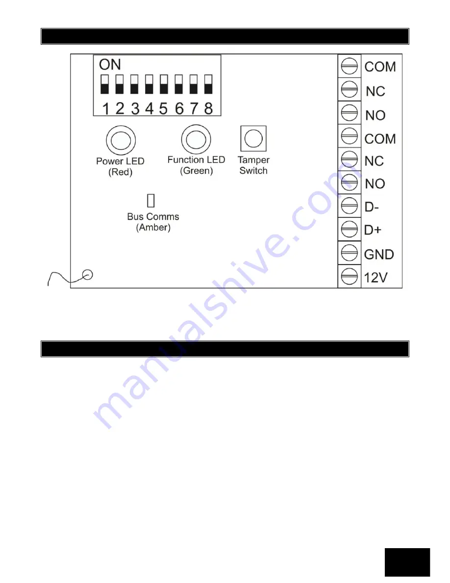
Section: 1
IDS X64 Remote Receiver 700-408-02A Issued August 2010
5
1.3
Wiring and Configuration
NOTE:
The amber LED will be a steady on when it is connected to the Bus. If it is off, then there is a problem.
The green LED flashes when in standby mode.
1.4
Installation
Choose a location for the Remote Receiver:
as high as possible
accessible for installation and maintenance
accessible for X64 wiring
accessible for wiring to controlled devices
suitable for antenna
1.
Straighten the antenna. It should not be kinked or coiled or rolled into a ball, and it should not lie
against metal. Hanging is best, but lying on wood is also fine.
2.
Mount the Remote Receiver, using fasteners (woodscrews etc) through the tabs at each end of
the base plate.
3.
Remove the Remote Receiver cover.
4.
The power and data terminals of the Remote Receiver should be connected to the
corresponding terminals of the X64 Alarm Panel, or the nearest keypad or zone expander. To
avoid mistakes, use sheathed cable with 4 colour-coded cores, and connect identically at each
end:
12V RED
GND BLACK
Содержание X64
Страница 1: ......
Страница 2: ...IDS X64 Remote Receiver 700 408 02A Issued August 2010 2...
Страница 22: ...IDS X64 Remote Receiver 700 408 02A Issued August 2010 22...
Страница 23: ...IDS X64 Remote Receiver 700 408 02A Issued August 2010 23...
Страница 24: ...IDS X64 Remote Receiver 700 408 02A Issued August 2010 24...


