background image

22 


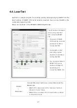
3)


Position


Field Size 

Set the maximum size for laser engraving.   


Range of Field Size is 120~150, the unit is mm. 


The size of output is changed if Field Size is changed.


Angle 

Set the rotation value for laser engraving. 


Range of Angle is 0~360, the unit is degree. 


The output is rotated as a value of Angle.


Offset X 

Set position to the right and left properly. 


Range of Offset X is -10~10, the unit is mm. 


The position of output is changed by left or right depending 
on this value.


Offset Y 

Set position to the up and down properly. 


Range of Offset X is -10~10, the unit is mm. 


The position of output is changed by up or down depending 
on this value. 


4)


Galvo


Negate 

Engrave after reflection of image across a defined axis. 

Scale 

Set the scale of image for each axis.   


Range of Scale is 0~100, unit is percentage (%). 

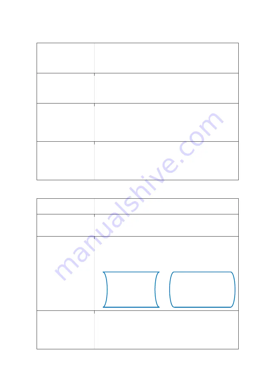
Ellipse 

Calibrate image result in shape of ellipse. 


Range of Ellipse is 0.875~1.125. 


The image is deformed depending on a value of Ellipse as 
below. 


Parallelogram 

Calibrate image result in shape of parallelogram. 


Range of Parallelogram is 0.875~1.125. 


The image is deformed depending on a value of 
Parallelogram as below. 

Содержание SMART-70X

Страница 1: ...1 SMART 70X User Manual Laser Engraver...

Страница 2: ...egistered trademarks are marks of their respective holders SMART 70 Design is a trademark of IDP Corp Ltd Return Materials Authorization In order to make a warranty claim you must contact an IDP Resel...

Страница 3: ...Caution 8 2 SMART0 70X Installation 9 2 1 Driver Installation 9 2 2 Stand alone installation 11 2 3 Installation with the SMART 70P 13 3 Engraving a card 17 3 1 LaserTest 17 3 2 SmartID 18 4 Utilities...

Страница 4: ...g encoding and laser engraving Picture 1 Example of combination for SMART 70X Key features of SMAR 70X are as follows Enable a fast and stable engraving with a high quality laser source Enable CLI Cha...

Страница 5: ...engraver is displayed It can be operated by buttons Window for monitoring It shows operation by eye Indicator LED It shows the simple status of module Blue Ready Green Operating Red Error Physical loc...

Страница 6: ...hole which air is inhaled Air Outlet The hole which air is exhaled Power Switch Turn On Off Power Plug 110 240V 50 60Hz Power plug Communication Port To communicate between SMART 70 modules USB Devic...

Страница 7: ...cks a power of laser for safety Camera It can check a graving Flipper It flip a card for engraving on both surfaces Card movement module It moves a card The encoder options are installed Door Open Sen...

Страница 8: ...evice is ON Otherwise the device may have a fault or cause fire Do not push a laser safety switch while the door is opened Otherwise the device cause burns or vision problem Do not disassemble or modi...

Страница 9: ...e installed in the PC SMART 70X provides a one time installation program for easy driver installation of all components Please install them as following the below steps 1 Run LaserInstall exe 2 Start...

Страница 10: ...10 3 Confirm a Windows Security 4 Complete drivers Click Install button when Windows Security windows is displayed STEP 3 Installation is completed Click Close button...

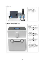
Страница 11: ...d SMART 70X as a below pictures for laser engraving only 5 Connection between SMART 70X and SMART 70I After install a binder below a SMART 70X connect a SMART 70I on the binder 6 Arrangement of module...

Страница 12: ...a 24V DC adapter to SMART 70I Connect the red communication cables to each module Connect each USB cable to SMART 70X and connect the opposite end to the PC 8 Power on Turn on the power in order of t...

Страница 13: ...MART 70X as a below pictures for printing and laser engraving 1 Connection between SMART 70X and SMART 70P After install a binder below a SMART 70X connect a SMART 70P on the binder 2 Connection betwe...

Страница 14: ...of cables Connect power cables red communication cables and USB cables as a left picture Connect a 100 240V 50 60Hz AC power to SMART 70X a 24V DC adapter to SMART 70P I Connect the red communication...

Страница 15: ...ck Menu button and find System Config Menu Click Select button then the Combination is displayed Click Arrow button and find Operation Mode Click Select button to change a Mode Click Arrow button to c...

Страница 16: ...16 7 Completion of installation All modules are installed normally if the colors of status LED are blue...

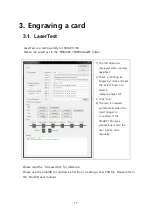
Страница 17: ...a Printing Engraving item and click the Select button to select a sample_single csd 3 Click Run 4 The card is inserted automatically when the input hopper is connected If the SMART 70X uses a stand a...

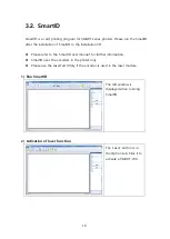
Страница 18: ...D Please refer to the SmartID user manual for further information SmartID uses the encoders in the printer only Please use the LaserTest Utility if the encoder is used in the laser module 1 Run SmartI...

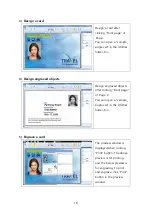
Страница 19: ...ed objects Design engraved objects after clicking Front page of Page 2 You can open a sample_ single csd in the Utilities folder too 5 Engrave a card The preview window is displayed when clicking Prin...

Страница 20: ...70X Utilities folder for adjusting a configuration of SMART 70X The left window is displayed after connecting a SMART 70X when running LaserConfig The power of SMART 70X should be connected and turne...

Страница 21: ...the power and speed when the text or barcode is engraved Range of Power is 0 100 it is percentage of the maximum value Range of Speed is 0 1600 the speed of movement of laser Line Set the power and sp...

Страница 22: ...ng on this value Offset Y Set position to the up and down properly Range of Offset X is 10 10 the unit is mm The position of output is changed by up or down depending on this value 4 Galvo Negate Engr...

Страница 23: ...ge is deformed depending on a value of Trapezoid as below 5 Load Save Load Default Load factory configuration values in the memory of SMART 70X To apply it click a Store button Reload Show the configu...

Страница 24: ...ng a LaserFirmware utility And SmartID or other Laser utilities should be closed before running a LaserFirmware 1 Run LaserFirmware The left window is displayed when running Laser Firmware utility aft...

Страница 25: ...ng Laser Firmware after connecting SMART 70X It works if Microsoft LifeCam Studio is shown in the first list box Click Search button after checking a connection status of SMART 70X if the camera is no...

Страница 26: ...am Focus Set the focus of camera by Focus When Auto Focus is checked it sets automatically Adjust a slider to show the image of printed card clear when it set manually White Balance Set the white bala...

Страница 27: ...ectina SMART 70X The power of SMART 70X should be connected and turned on before running LaserTest The SmartID or other laser utility program should be closed before running LaserTest The Connection f...

Страница 28: ...contact contactless smart card should be adjusted to the encoding position For Printing and Engraving select a CSD file to design in SmartID When checking Error card handling the error card is moved t...

Страница 29: ...l SMART 70 Output Hopper Error Card Bin Max 20 Cards System Display LCD LED Control Panel 4 Buttons Vision Camera Laser Engraving Monitoring Supported Platforms Microsoft Windows 7 8 10 Communication...

Отзывы:

Похожие инструкции для SMART-70X