
Idle Smart Installation Guide
Page 4
Version 1.5 – March 2014
□
Step 10: Connect Base Unit with Diagnostic Port
Locate the CanBus connector and wire. Install the 9-pin round connector to the Diagnostic port. Run the remaining
wire behind the dash to the Base Unit and connect.
□
Step 11: Install Interior Temperature Sensor
Locate the gray-sheathed wire on the Harness and connect to the Interior Temperature Sensor. Feed wiring behind
the dash, along the floorboards on the driver side and back to the bunk. Connect the temperature sensor to the gray-
sheathed wire. The sensor can be placed anywhere but it is recommended that it be close to the driver’s head in the
bunk area so that it measures the most appropriate temperature. It is also recommended to run the black Ethernet
cord with the gray-sheathed temperature wire together with the gray-sheathed wire to save time on step 14. Coil and
tuck any extra cord.
□
Step 12: Install Outside Temperature Sensor
Locate the black-sheathed wire on the Harness and the temperature extension cable (included in the Idle Smart
box). Plug the extension cable into the black-sheathed wire connector. Run the whole cable behind the dash,
through the firewall, and along the frame rail on the under side of the truck to the end of the frame. Secure with the
provided zip ties. Connect the Outside Temperature Sensor to the cable. Make sure the tip of the temperature
sensor is not touching any metal to ensure the most accurate outside temperature reading is captured. Coil and
tuck any extra cord.
□
Step 13: Test basic operation of Idle Smart
Prior to mounting the display unit, run through a test scenario to ensure that Idle Smart was properly installed and
working correctly. If not done so already, plug the black Ethernet cord into the base unit and connect it to the display
unit. The display unit should power on. If any of the safety switches or temperature sensors are not connected
properly, faults will appear on the screen immediately. If everything is correctly connected, the temperature screen
will appear. Click the timer softkey, and change the timer from off to 6:00 minutes. For this basic operational test,
adjust the target temperature (using the arrow keys) to either 50° or 80°. This setting should provide the greatest
difference between current inside temperature and target temperature to ensure the temperature is outside of the
range to start the truck. Idle Smart will now start the truck and the timer should start to count down to 0:00. After the
truck has started and the timer hits 5:00, Idle Smart should increase the RPMs. If the truck did not idle up, then turn
off Idle Smart by unplugging the Ethernet cord from the display unit and proceed back to step 8 to ensure that the
wires are correctly connected. If the truck did idle up correctly, Idle Smart should be running properly. When the
timer hits 2:00 the truck should idle back down to base idle. At 0:00, the truck should shut down. If the startup, idle
up, idle down, and shut down occurred properly, then the test procedure is complete. Change the timer mode back
to off from 6:00 minutes. Adjust the target temperature back to its original setting. This 6-minute test procedure is
used to ensure that the 5-minute shut off is bypassed correctly (if it is enabled).
*If the truck does not idle up correctly per this process, call Idle Smart for troubleshooting help. (913) 744-4353.
□
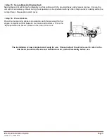
Step 14: Mount Idle Smart Display Unit
Locate a suitable flat, vertical surface for mounting the Idle Smart Display Unit. Recommended location is in the
bunk area within easy access for the driver during rest periods. Attach the RJ45 connector to the mounting plate
with the provided screws. Drill a 1” hole in the bulkhead where the Display Unit will be placed. This hole will
facilitate the RJ45 connector provided on the mounting plate and will be covered by the mounting plate when
complete. If not already done in step 11, Run the black modular cord from the Base Unit behind the dash, up the
side of the windshield tucking the cord neatly under the interior paneling or otherwise securing it to the cabin. This
cord should be run in this fashion along the interior overhead and behind the bulkhead to the 1” hole. Connect the
end of the black modular cord to the backside of the RJ45 connector on the mounting plate. Using the provided
screws, secure the mounting plate in the desired location so the RJ45 connector slides easily within the drilled hole.
Connect the provided coil cord from the mounting plate to the back of the Display Unit. The Display Unit mounts
securely to the mounting plate with the Dual Lock™ strips provided on the mounting plate and rear block of the
display unit. The Display Unit is designed to be removable from the mounting plate and portable within the bunk
area tethered by the coil cord.