


Part 1 – Introduction
20
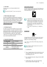
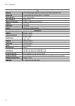
1
ID
Button
Used to assign remote control ID values.
No additional remote control assignment is necessary
if the system's ID is 0. If the system's ID is a number
between 1 and 99, however, you will need to press the
ID button and then press the system ID number on
the remote control. If the system's ID is set in double
digits, press each digit button consecutively. The
(remote control) icon will appear on the upper right
corner of the NVR screen (status indication area) to
indicate successful system-to-remote control pairing.
If using multiple systems, it's possible to control all the
units with a single remote control as long as all the
system IDs are 0. For more information on system IDs,
refer to the
System Setup in the operation manual
.
2
PANIC
Button
Pressing this button displays the icon and
commences recording irrespective of the current
schedule.
Press the button again to deactivate Panic Recording
mode.
3
Camera
Buttons
Pressing the
Camera
button while in Live or Playback
mode displays images from the selected camera in full
screen. To select a camera whose channel is made up
of two digits, enter the digits in sequence using the
number keys.
4
STATUS
Button
Displays event, recording device and network statuses.
5
LAYOUT
Button
1x1 > 2x2 > 1+5 > 1+7 > 3x3 > 4x4 > 5x5 > 6x6
6
PTZ
Control Buttons
Used in PTZ mode to zoom in/out on the screen and
to shift focus between a nearby point and a far away
point.
7
REGISTER MODE
Button
Used in Live mode to access Camera Registration
mode.
8
THUMBNAIL
Button
Used in Playback mode to access Thumbnail Search
mode. Thumbnail Search mode displays thumbnails of
video recordings and allows you to search recordings
based on date, time, minutes and seconds parameters.
9
CALENDAR
Button
Displays a video recording playback screen that
includes a calendar.
0
KEYLOCK
Button
Locks out all remote control keys. To unlock, press the
button again.
!
SETUP
Button
Pressing the
SETUP
button while in Live mode
displays the setup menu.
Used to pause Live screen.
#
LOG
Button
Displays system log window and allows you to search
the log.