


Part 1 – Introduction
10
Overview
Front Panel
1
2
3
4
5
6
7
8
9
0
1 2 3 4 5 6
7
8
0
9
9
1
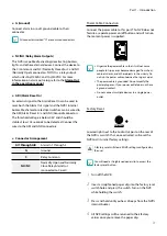
Panic Recording
Button
2
Alarm
Button
3
PTZ
Button
4
Layout
Button
5
Search Mode
Button
6
Menu
Button
7
Camera
Buttons
8
Arrow
and
Playback
Control Buttons
9
LEDs
0
USB Ports
•
Some buttons have more than one function.
•
Remote control sensor is located on the far left side of the front panel. Ensure that the sensor remains unobstructed at all
times. If obstructed, the sensor might not be able to receive remote control signals.
•
Placing a Wi-Fi, Bluetooth, or any other wireless communication device near the NVR may interfere with remote control
signal transmission.
•
Access various windows and menus using a USB mouse as you would on a personal computer.
•
For easier system configuration, a USB mouse is recommended.