background image

29

Three-position Enabling Switches/Grip Style Three-position Enabling Switches

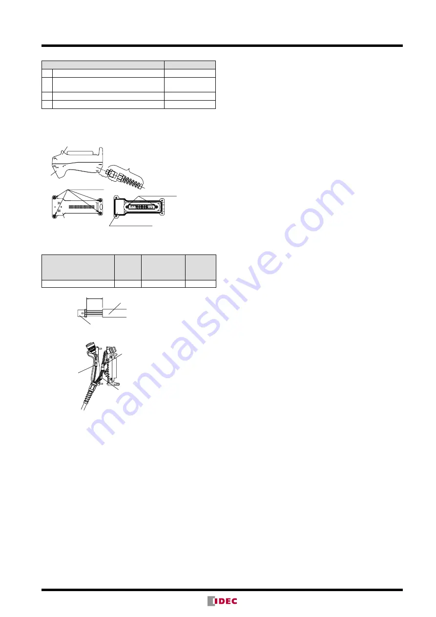
Recommended Tightening Torque

Parts for tightening

Torque

A Base and rubber kit (M4 screw × 4)

1.1 to 1.3 N·m

B Cable gland and grip style enabling 

switch

2.7 to 3.3 N·m

C Cable gland

2.7 to 3.3 N·m

D HE2B Enabling Switch (M3 screws × 2) 

*

0.5 to 0.8 N·m

Note:  The recommended tightening torques of B and C are for 

the supplied cable gland. When using another cable gland, 

refer to the tightening torque of the cable gland used.

For replacing HE2B enabling switch or rubber boot only

Rubber Boot Kit

Cable Gland

Base

Base

B

C

D (M3 scew × 2)

A (M4 scew × 4)

Rubber Boot Kit

HE2G (internal connector)

Wire Length inside the Switch

Grip 

Style 

Enabling 

Switch

Momentary 

Pushbutton/Key 

Selector Switch

Emergency 

Stop 

Switch

Wire stripping length L1 (mm)

20

60

75

Cable gland for
emergency stop switch

Cable gland for
momentary pushbutton/
key selecetor switch

Cable gland for
grip style enabling switch 

L1

Sheath

<Example>

Applicable cable gland
on cable side

• Applicable wire size for the cable gland on cable side

• 0.05 to 0.86mm

2

 (AWG18 to 30): Check the compliance with 

receptacle and contact. 

Tool: 1762846-1 (manual tool)

Note:  When using stranded sires, make sure that loose wires do 

not cause short circuit. Also, do not older the terminals 

to prevent loose wires. Use copper wire of 60°C or 75°C 

temperature rating in order to comply with UL508. Observe 

the requirements of GS-ET-22: 2003, 4.2.6 for wiring.

Operating Instructions

HE2B/HE3B/HE5B/HE6B/HE1G/HE1G-L/HE2G

• To achieve a high level of safety, connect the two contacts of the 

3-position switch to a disparity detection circuit (e.g., safety relay 

module) (ISO 13849-1, EN 954-1).

• Because two contacts are designed to operate independently, 

pressing the edge of a button turns on one contact earlier than 

the other contact, causing a delay in operation. To avoid this, 

always press the center of the button.

HE1B/HE2B/HE3B/HE5B/HE6B/HE1G/HE1G-L/HE2G

• 3-position enabling switches output ON signals in position 2. 

Sys tems must be designed to enable machine operation when 

the 3-position enabling switch is in position 2 only.

• Perform a risk assessment in actual applications as strong force 

may be applied to the switch when depressed to position 3.

• Perform a risk assessment for the shape and structure of the 

part where the enabling switch is installed, to prevent unintended 

operation of the enabling switch. For example, an enabling 

switch protruding from the teach pendant may result in an unin-

tended operation of the enabling switch.

• Strong force may be applied to a 3-position enabling switch 

when pressed to position 3. Provide sufficient strength to the 

part where 3-position enabling switches will be installed.

Содержание HE1B Series

Страница 1: ...Enabling Switches Grip Style Enabling Switches...

Страница 2: ...the switch is lightly pressed and held in the mid posi tion position 2 Because it disables machine operation when released position 1 or further depressed position 3 by a panicked operator the safety...

Страница 3: ...a safety relay module International standards on enabling switches IEC 60204 1 1997 9 2 4 Where it is necessary to suspend safeguarding e g for set ting or maintenance purposes a mode selection devic...

Страница 4: ...4 4 4 4 Applicable Standards IEC EN60947 5 1 IEC EN60947 5 8 T V approval GS ET 22 T V approval UL508 UL recgonized CSA C22 2 No 14 c UL recognized GB14048 5 CCC approval IEC60947 5 1 EN60947 5 1 T V...

Страница 5: ...s a part of a system it shall be designed to allow motion when actuated in one position only In any other position motion shall be stopped ANSI RIA R15 06 4 7 3 Enabling device The pendant or teaching...

Страница 6: ...EN60947 5 8 GS ET 22 UL508 CSA C22 2 No 14 screw terminal Size Operation Force Monitor Switch for Position Detection Additional Switch With Without Small Standard Light Light Standard Note 2 Note 1 M...

Страница 7: ...gnized IEC EN 60947 5 1 IEC EN 60947 5 8 T V approval IEC EN60947 5 1 UL508 UL recognized CSA C22 2 No 14 c UL recognized Applicable Standards for Use ISO 12100 1 2 EN12100 1 2 IEC 60204 1 EN 60204 1...

Страница 8: ...al When pressed to position 3 2 Mounting Hole Layout 24 0 2 15 min 2 8 9 min Insert the nuts supplied with the switch Screw size M2 6 mounting panel thickness 5 to 6 Mounting Screw Length Mounting pan...

Страница 9: ...B M211PN10 10 2 2 2 HE2B M222 HE2B M222 1 HE2B M222PN10 10 With Rubber Boot Rubber Boot Material Silicon Rubber Color B black Y yellow 2 0 0 HE2B M200P HE2B M200P 1 HE2B M200P PN10 10 2 1 1 HE2B M211P...

Страница 10: ...mes 5 to 55 Hz amplitude 0 5 mm Damage limits 16 7 Hz amplitude 1 5 mm Terminal Style Solder terminal Applicable Wire 1 cable 0 5 mm2 maximum Terminal Soldering Heat Resistance 310 to 350 C 3 seconds...

Страница 11: ...5 5 13 5 5 69 68 69 7 14 2 11 5 19 90 14 8 6 5 5 Without Rubber Boot With Rubber Boot M3 nuts are supplied with the HE2B enabling switch M3 nuts are installed in the rubber boot Mounting Hole Layout...

Страница 12: ...cable load reference value 5V AC DC 1 mA Applicable range is subject to the operating conditions and load Specifications Applicable Standards IEC EN60947 5 8 T V approval IEC EN60947 5 1 UL508 UL reco...

Страница 13: ...th 2 8 0 5t 8 15 R 1 5 5 13 1 38 1 22 2 16 8 5 14 5 8 5 24 6 12 3 33 1 51 2 Anti rotation Ring Rubber Boot 3 2 5 5 5 30 3 R2 13 39 11 5 27 5 34 5 9 25 5 15 2 15 5 9 5 8 25 39 5 14 5 54 R1 20 5 Solder...

Страница 14: ...1mA Applicable operation area depends on the operating conditions and load Specifications Applicable Standards IEC EN60947 5 8 T V approval IEC EN60947 5 1 UL508 UL recognized CSA C22 2 No 14 c UL rec...

Страница 15: ...ween NO1 and C1 NO2 and C2 Note For OFF ON OFF 3 position switches use NO and C terminals NC terminal is not used Mounting Hole Layout Recommended Tightening Torque for Locking Ring 0 29 to 0 49 N m U...

Страница 16: ...ch hous ing only For enabling switch see the HE5B specifications on page 14 The following switches can be installed on the grip style enabling switch housing to be used as hand held switches AB6M push...

Страница 17: ...tor switch 02 2 contacts of depress monitor switch 20 and 02 are not standard Contact IDEC for details Accessories Replacement Rubber Boot Material Color Part No Ordering No Package Quantity Silicon R...

Страница 18: ...V monitor switch 250V Rated Thermal Current Ith 3A Rated Voltage Ue 30V 125V 250V Rated Current Ie 3 position switch AC Resistive Load AC 12 0 5A Inductive Load AC 15 0 3A DC Resistive Load DC 12 1A I...

Страница 19: ...yblend gray HE1G 20MB 1N Note 1 Silicon rubber Can be used in general factories Remains flexible at cold temperatures Suitable to applications in a wide operating temperature range Note 2 NBR PVC poly...

Страница 20: ...ew Tightening Torque 0 5 to 0 6 N m Degree of Protection HE1G 21SM IP66 IEC 60529 HE1G 20ME IP65 IEC 60529 HE1G 20MB IP65 IEC 60529 HE1G 21SMB IP65 IEC 60529 Conditional Short circuit Current 50A 250V...

Страница 21: ...with grip style enabling switch Part No SKINTOP BS M20 1 5 LAPP Cable Gland supplied with grip style enabling switch Part No SKINTOP BS M20 1 5 LAPP Accessories Mounting Bracket for hanging grip style...

Страница 22: ...ternal Connector HE1G L20MCE NBR PVC Polyblend gray Terminal Block HE1G L20ME 1N Internal Connector HE1G L20MCE 1N Momentary Pushbutton Switch 2NO AB6M M2PB Silicon Rubber yellow Terminal Block HE1G L...

Страница 23: ...0 6 N m Degree of Protection HE1G L21SM IP66 IEC 60529 HE1G L20ME IP65 IEC 60529 HE1G L20MB IP65 IEC 60529 HE1G L21SMB IP65 IEC 60529 Conditional Short circuit Current 50A 250V Use 250V 10A fast blow...

Страница 24: ...rt No 3 Position Switch Monitor Switch Additional Switches Note 1 Emergency Stop Switch Switch A Switch B Pilot Switch green C 2 contacts With 1NC Without Silicon Rubber Yellow Note 2 Solder Terminal...

Страница 25: ...oot 25 to 60 C no freezing NBR PVC Polyblend rubber boot 10 to 60 C no freezing Relative Humidity 45 to 85 no condensation Storage Temperature 40 to 80 C no freezing Pollution Degree 3 Contact Resista...

Страница 26: ...3 B2 B1 A2 A1 B2 B1 3 position switch switch side connector Tyco Electronics D 1200D Series Tab housing 1 1903130 2 4 pin connector 1 1903130 3 6 pin connector Tab contact 19303116 2 Terminal Arrangem...

Страница 27: ...sure in an inap propriate direction otherwise the waterproof function can be dam aged Wiring Instructions HE1B HE2B HE3B HE5B HE6B Enabling Switch Applicable wire size 0 5 mm2 maximum 1 pc Solder the...

Страница 28: ...p 20 2mm Applicable Connector on Cable Side Applicable Wire Size 0 05 to 0 86mm2 AWG18 to 30 Check the compliance with receptacle and contact Tool 1762846 1 manual tool Observe the requirements of GS...

Страница 29: ...uit Also do not older the terminals to prevent loose wires Use copper wire of 60 C or 75 C temperature rating in order to comply with UL508 Observe the requirements of GS ET 22 2003 4 2 6 for wiring O...

Страница 30: ...th Plastic Holder HS5B Interlock Switch HS5E Interlock Switch Description Part No Actuator with plastic holder for HE1G HE1G L HE2G HE9Z GP15 Note The HE1G HE1G L HE2G grip style enabling switches and...

Страница 31: ...Otherwise the HE9Z GP15 actua tor will be deformed Mounting Surface for Interlock Switch UP DOWN Correct Incorrect Do not install the grip style enabling switch and the interlock switch in an area sub...

Страница 32: ...ervice tw idec com Hong Kong IDEC Izumi H K Co Ltd Tel 852 2803 8989 info hk idec com China Shanghai IDEC Shanghai Corporation Tel 86 21 6135 1515 idec cn idec com China Shenzhen IDEC Shenzhen Corpora...

Отзывы: