


24
Viceroy GT -
Installation & Servicing
INSTALLATION
vic7109
3
vic7108
2
1
2
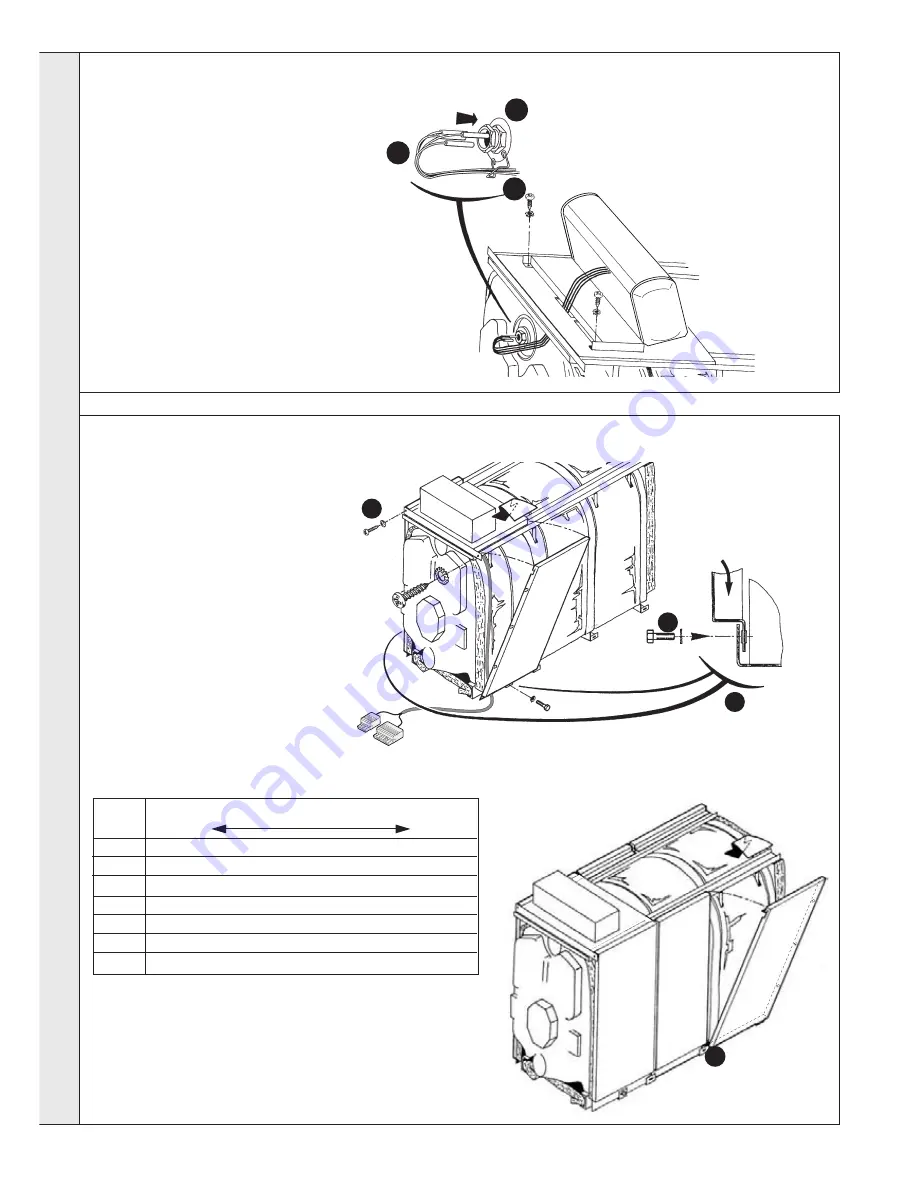
33 INSTALLING THE SENSORS AND ROUTING THE BURNER CABLE
1.
Route the burner cable inside the
front edge return of one side of the
casing side panels opposite the
burner hinges. (RH side shown for
clarity. See Frame 34.)
2.
Insert the sensors into the sensor
pocket.
3.
Loop the sensor leads back over the
sensor pocket.
4.
Secure the leads with the spring clip.
34 ASSEMBLING THE CASING SIDE PANELS
1.
Position the front side panels
(length 520) in the lower
casing supports, then hook
onto the wiring ducts.
2.
Fix at the sides onto the lower
casing supports using M5x12
bolts and lock washers and at
the front top panel using self
tapping screws and lock
washers.
3.
Fit the remaining side panels
in the order given in the table
below. Position each panel in
the lower casing supports
then hook onto the wiring
duct.
3
4
2
Boiler
Side panel width
Front
Rear
GT 8
520(IE10)
930(IE12)
GT 9
520(IE10)
480(IE13
610(IE14)
GT 10
520(IE10)
480(IE13)
770(IE11)
GT 11
520(IE10)
480(IE13)
930(IE12)
GT 12
520(IE10)
480(IE13)
480(IE13)
610(IE14)
GT 13
520(IE10)
480(IE13)
480(IE13)
770(IE11)
GT 14
520(IE10)
480(IE13)
480(IE13)
930(IE12)
INST
ALLA
TION
Содержание Viceroy GT 8
Страница 38: ...38 Viceroy GT Installation Servicing NOTES ...
Страница 39: ...39 Viceroy GT Installation Servicing NOTES ...