background image

5

Harrier GTE - 

Installation & Servicing

GENERAL

FLUE INSTALLATION

IMPORTANT
It is the responsibility of the installer to ensure, in practice, that
products of combustion discharging from the terminal cannot re-
enter the building or any other adjacent building through
ventilators, windows, doors, other sources of natural air
infiltration, or forced ventilation / air conditioning.

If this should occur the appliance MUST be turned OFF, labelled
as 'unsafe' and corrective action taken.

The flue must be installed in accordance with the appropriate
standards listed on page 4.

WATER CIRCULATION SYSTEM

The system pump MUST be connected to the boiler.

The boiler must NOT be used for direct hot water supply.  The
hot water storage cylinder MUST be of the indirect type.

The appliances are NOT suitable for gravity central heating nor
are they suitable for the provision of gravity domestic hot water.

The hot water cylinder and ancillary pipework, not forming part of
the useful heating surface, should be lagged to prevent heat
loss and any possible freezing - particularly where pipes run
through roof spaces and ventilated underfloor spaces.

The boiler must be vented.

Draining taps MUST be located in accessible positions, which
permit the draining of the whole system - including the boiler
and hot water storage vessel.  They should be at least 1/2" BSP
nominal size and be in accordance with BS. 2879.

The central heating system should be in accordance with the
relevant standards listed on page 4.

Due to the compact nature of the boiler the heat stored within the
castings at the point of shutdown of the burner must be
dissipated in order to avoid overheating.  In order to allow pump
operation after burner shutdown the boiler control system
should incorporate a pump overrun device.

WATER TREATMENT FOR HOT WATER AND
HEATING BOILERS

There is a basic need to treat the water contained in all heating
and indirect water systems, particularly open vented systems.  It
is assumed, incorrectly, that because boilers are operating in
conjunction with what is apparently a closed circuit an open
vented system will not, under normal circumstances, allow
damage or loss of efficiency due to hardness salts and
corrosion once the initial charge of water has been heated up a
few times.

1mm of lime reduces the heat transfer from metal to water by
10%.

In practice the deposition of these salts is liable to cause noises
from the boiler body or even premature boiler failure.  Corrosion
and the formation of black iron oxide sludge will ultimately result
in premature radiator failure.

Open vented systems are not completely sealed from the
atmosphere if proper venting and expansion of system water is
to be achieved.  The same tank is used to fill the system with

water and it is through the cold feed pipe that system water
expands into the tank when the boiler passes heat into the
system.

Conversely, when the system cools, water previously expelled is
drawn back from the tank into the system together with a quantity
of dissolved oxygen.

Even if leakage from the heating and hot water system is
eliminated there will be evaporation losses from the surface of
the tank which, depending upon ambient temperature, may be
high enough to evaporate a large portion of the system water
capacity over a full heating season.

There will always be corrosion within a heating or hot water
system to a greater or lesser degree, irrespective of water
characteristics, unless the initial fill water from the mains is
treated.  Even the water in closed systems will promote
corrosion unless treated.  For the reason stated, Caradon Ideal
Limited
 strongly recommend that when necessary the systems
is thoroughly cleaned, prior to the use of stable inhibitor, which
does not require continual topping up to combat the effects of
hardness salts and corrosion on the heat exchangers of the
boiler and associated systems.

Caradon Ideal Limited advise contact directly with specialists on
water treatment such as:

GE Betz Ltd, Sentinel Division, Foundry Lane,
Widnes, Cheshire, WA8 8UD,
Tel: 0151 424 5351

Fernox Manufacturing Co. Ltd., Cookson Electronics,
Forsyth Road, Sheerwater, Woking, Surrey, GU21 5RZ
Tel: 01799 521 133

Salamander Engineering Ltd., Unit 24, Reddicap Trading Estate,
Sutton Coldfield, West Midlands, B75 7BU
Tel: 0121 378 0952

ELECTRICAL SUPPLY

WARNING

This appliance must be earthed.

The control system requires a 230V - 50Hz mains supply.

Wiring external to the appliance MUST be in accordance with the
current I.E.E. (BS7671) Wiring Regulations and any local
regulations which apply.

Burner and Pump

These may be 1ph or 3ph.  Refer to manufacturer's instructions.

The point of connection to the mains should be readily
accessible and adjacent to the boiler.

LOCATION OF THE BOILER

The boiler must stand on a non-combustible floor (i.e. concrete
or brick) which must be flat, level and of a suitable load bearing
capacity to support the weight of the boiler (when filled with
water) and any ancillary equipment.

If the boiler is mounted on a plinth then the dimensions must
exceed the plan area of the boiler by at least 75mm on each
side.

The boiler must not be fitted outside.

Содержание GTE 5

Страница 1: ...When replacing any part on this appliance use only spare parts that you can be assured conform to the safety and performance specification that we require Do not use reconditioned or copy parts that h...

Страница 2: ...onomisers etc are directly connected to these appliances unless covered by these Installation and Servicing Instructions or as otherwise recommended by Caradon Ideal Limited in writing If in doubt ple...

Страница 3: ...t boilers offering high efficiency operation ease of maintenance fuel flexibility and low emissions Suitable for oil or gas operation the Harrier GTE range is supplied in a choice of 5 standard models...

Страница 4: ...est code for heating boilers for atomizing oil burners 73 23 EEC Low voltage directive Relevant standard is EN60335 1 89 336 EEC Electromagnetic Compatibility Directive Relevant standards are EN50081...

Страница 5: ...and the formation of black iron oxide sludge will ultimately result in premature radiator failure Open vented systems are not completely sealed from the atmosphere if proper venting and expansion of s...

Страница 6: ...re as shown Rear 1000mm or adequate space to make the flue connections and access to the flue sample point drain connection flue and smokehood cleanout doors and any safety or control devices Sides On...

Страница 7: ...actor fan in the same room as the boiler or in an adjacent communicating room can in certain conditions adversely affect the safe operation of the boiler Where such a fan is already fitted or if it is...

Страница 8: ...ng down the boiler plant if a potentially hazardous situation should arise Examples of such situations are low water level and operating pressure or excessive pressure within the system Depending on c...

Страница 9: ...Heating return 3 3 bar safety valve and pressure gauge 4 Flow switch if necessary 5 Air separator 6 Automatic venting valve 7 Valve 8 Shunt pump required for all models 9 Expansion tank 10 Draining v...

Страница 10: ...flues for GAS fired appliances are quoted in BS 6644 and IGE UP 10 whilst BS 5410 Pt 1 similarly applies to OIL fired boilers The table below contains the minimum dimensions of the flue required for e...

Страница 11: ...r assembly Tools required not supplied Phillips head screwdriver Wide flat screwdriver 13 and 17mm spanners hammer Silicone glue JDTE assembly tool Simplified assembly tool The assembly of any optiona...

Страница 12: ...into the slots in the side components 15 FITTING THE BASE FRAME INSULATION 1 Locate the insulation between the sides and end with the black fabric on the underside 2 2 fal5982 1 1 2 2 har5983 2 Assem...

Страница 13: ...h the rear section 4 Pass the rods through the rear section and secure both ends with the 4 washers and M12 nuts This may be conducted after preparing the section Frame 17 and fitting thermocord Frame...

Страница 14: ...to the groove 3 Cut it to the correct length 4 Repeat for intermediate sections 19 ASSEMBLING THE INTERMEDIATE SECTIONS 1 Place the first intermediate section onto the base frame 2 Fit the connections...

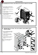
Страница 15: ...15 Harrier GTE Installation Servicing INSTALLATION 20 ASSEMBLING THE INTERMEDIATE SECTIONS CONT D Proceed likewise for other intermediate sections A 20 cm har5993 1 3 2 4 5 6 8 7 INSTALLATION...

Страница 16: ...any surplus silicone 6 Remove the assembly tool 7 Level the boiler by adjusting its feet 22 PREPARATION FOR FITTING THE FLUE CLEANOUT AND BURNER DOORS FOR RH OPENING 1 Screw in and tighten all the stu...

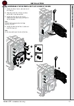
Страница 17: ...evenly with four M12 nuts and washers 3 Position the flue cleanout door hinge bracket as shown and secure with two M12 nut and washers Note For left hand opening position the hinge bracket on the left...

Страница 18: ...or models GTE 7 GTE 8 and GTE 9 will contain two sizes of baffle Use only the 570 mm long ones and discard the shorter ones 4 In all cases the baffles should be pushed in to be flush with the front ha...

Страница 19: ...ug 2 Screw the threaded bush with the sensor pocket into the upper connection and the plug into the lower connection har7001 1 2 2 27 FITTING THE SMOKEHOOD 1 Screw the four M8 studs into the rear sect...

Страница 20: ...d and tapped connections of the sections pipes and drain cock with thread sealing tape or compound not supplied 2 Screw the flow and return pipes and the drain cock into the rear section Ensure the ta...

Страница 21: ...6 Close the vent valve 7 Disconnect the supply water 8 Connect the pressure system water 9 Open the fill valve 10 Pressurise the boiler Maintain pressure for at least 10 minutes Any drop in pressure...

Страница 22: ...the sides and tuck underneath 2 Models GTE 8 and GTE 9 After fitting the front insulation similarly place the rear section 3 Secure the two sections together using the clips provided 4 All Models Pla...

Страница 23: ...1 31 INSTALLING THE CASING CROSSBAR SUPPORTS 1 Fit four edge clips to the crossbars 2 Secure the crossbars to the front and rear section lugs using the M12 bolts washers shakeproof washers and nuts No...

Страница 24: ...ont edges can be identified by the projection 2 Engage the panel bottom onto the base frame 3 Lift the panel to its vertical position 4 Secure the top edge to the front crossbar support using M8 bolts...

Страница 25: ...corner with four self tapping screws and shakeproof washers Note If a pressure relief valve has already been fitted in the flow connector or if the panel is being replaced on a completed installation...

Страница 26: ...rough the left or right hand opening in the top front panel 2 Route the burner leads through the other opening in the top front panel 3 Lower the control panel onto the location buttons nearer the fro...

Страница 27: ...L FD168 Deluxe 1 Route the sensors through the left or right hand opening in the top front panel 2 Route the burner leads through the other openings in the top front panel 3 Lower the control panel on...

Страница 28: ...LING THE FRONT PANEL 1 Push the panel onto the location buttons and slide the panel downwards har7024 41 ASSEMBLING THE REAR TOP PANEL har7025 1 2 2 1 1 Engage the location buttons on the top panel in...

Страница 29: ...carton contains 1 control panel complete with burner connection harness The control panel incorporates a boiler thermostat controller a thermometer and a safety thermostat The boiler thermostats one...

Страница 30: ...n access to the connection strip unscrew the three screws on the rear of the control panel and open the panel 2 Pass the connecting cables to the control panel through the two cut outs in the rear pan...

Страница 31: ...n the rear panel of the boiler and route them to the front via the cable channel s See Frame 35 5 Pass the cables into the control panel through the rectangular openings in the front top panel 6 Secur...

Страница 32: ...H Pump not supplied 3x 0 75 mm 2 min Shunt Pump not supplied har7053 Remove white link wire 50 FITTING OPTIONAL FEATURES FD168 Deluxe Control Panel Hour Run Meters IC8 One or two optional hour run met...

Страница 33: ...ge 1 boiler thermostat TCH2 Stage 2 boiler thermostat TS Safety thermostat VA Alarm indicator VA TS Safety thermostat alarm indicator VB1 Stage 1 operating indicator VB2 Stage 2 operating indicator ZB...

Страница 34: ...other end VIS5146 7 pin plug for one stage burners or stage 1 of two stage burners 4 pin plug for stage 2 of the burner Terminal block for connecting to the control panel Note If the electrical chara...

Страница 35: ...ire Connector No From Connection to the Burner Control Box Terminal No L1 7 Permanent Live supply from the safety thermostat Burner main supply g y Earth connection Earth connection N 6 Neutral taken...

Страница 36: ...C For ON OFF burners use 1st stage thermostat only For two stage burners set 2nd stage 5 C below 1st stage setting Built in stops may be reset See Frame 56 Factory set at 75 C 4 Boiler Thermometer In...

Страница 37: ...mp Summer stops the heating pump 3 Three Position Switch TESTSTB When held in the pressed momentary use position it tests the safety thermostat Note If two stage burner control fitted operation will c...

Страница 38: ...r 20 minutes and for gas fired boilers check the gas rate Table 1 11 Refer to the burner instructions for specific operating features 12 Set the boiler thermostats 3 or Deluxe model 6 to appropriate s...

Страница 39: ...solate the mains supply to the boiler and burner 4 Disconnect the cable and supply pipe to the burner 5 Open the combustion chamber and flue way doors by removing the 8 nuts 6 Remove the flue way baff...

Страница 40: ...system hot examine all water connections for soundness Check the gas rate and measure the combustion CO CO2 content Complete the boiler log book Carry out functional checks as appropriate 66 SERVICIN...

Страница 41: ...41 Harrier GTE Installation Servicing NOTES...

Страница 42: ...42 Harrier GTE Installation Servicing NOTES...

Страница 43: ...43 Harrier GTE Installation Servicing NOTES...

Страница 44: ...ing improvement in the design and performance of its products The right is therefore reserved to vary specification without notice The Ideal Boilers Technical Training Centre offers a series of first...

Отзывы: