30
Harrier GTE -
Installation & Servicing
INSTALLATION
3
4
1
2
5
6
7
8
9
10
11
12
L
4
N
ALI
5
6
7
8
9
10
11
12
230 V / 50 Hz
N
L1
T1
T2
T6
T7
T8
S3
VA
3 x 0,75 mm
2
har7049
44 ELECTRICAL CONNECTIONS
WARNING. The electrical connections must be made by a
qualified professional. The electrical wiring has been
carefully checked in the factory and the internal connections
of the control panel must not be modified in any event.
The electrical connections should be made following the
information shown on the electrical diagrams delivered with
the unit and the directions given in the instructions.
The electrical connection must comply with standards in
force. The equipment must be powered by a circuit
containing a remote double-pole switch with opening > 3mm.
WARNING. The boiler must be earthed.
All connections must be made using the terminal blocks
provided for this purpose at the back of the boiler control panel.
Connections cables are brought inside the boiler through cut-
outs provided in the boiler back panel, which are large enough
for use of commercially available conduit if required.
These cables are secured at the back of the control panel
using cable clamps (cable clamps supplied in a separate
pack) that are to be installed on the sheet metal.
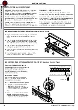
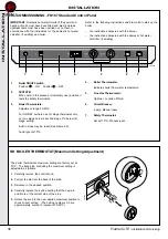
45 BASIC CONNECTIONS - FD167 Standard Control Panel
1. To gain access to the connection strip, unscrew the three
screws on the rear of the control panel and open the
panel.
2. Pass the connecting cables to the control panel through
the two cut-outs in the rear panel of the boiler and route
them to the front via the cable channels. (See Frame 35).
3. Pass the cables into the control panel through the
rectangular opening sin the front top panel.
4. Secure the cables to the base of the control panel with the
cable clamps.
5. Connect the main supply to terminals 1, 2 and 3 of the
connecting strip as shown. (See also Frame 46)
3
5
1
4
2
12
11
10
9
8
7
6
5
4
VA
S3
T8
T7
T6
T 2
T1
L1
N
230V
50H
z
L
N
A
L
I
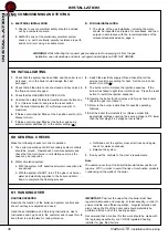
46 CONNECTING OPTIONAL FEATURES - FD167 Standard Control Panel
Flow Switch / Optional Safety Devices
If a flow switch or other safety control is to be
included in the system, connect the
device(s) in series in the safety circuit, (i.e.
between terminal 5 of the connecting strip
and burner terminal L1).
Burner Alarm Indicator
If an alarm indicator is to be included it
should be connected across terminal 12
(live) and terminal 4 (neutral).
Safety Thermostat Alarm Indicator System
1. The unused insulated terminal on the
safety thermostat may be used to
connect an alarm signal. (This terminal
becomes live if the safety thermostat
trips.)
2. Remove the insulation and connect the
live wire from the alarm indicator to the
unused terminal using a suitable spade
connector and the neutral to terminal 4.
12
11
10
9
8
7
6
5
4
VA
S3
T8
T7
T6
T 2
T1
L1
N
230V
50Hz
L
N
ALI
har7050
INST
ALLA
TION
Содержание GTE 5
Страница 41: ...41 Harrier GTE Installation Servicing NOTES...
Страница 42: ...42 Harrier GTE Installation Servicing NOTES...
Страница 43: ...43 Harrier GTE Installation Servicing NOTES...

