39
xtra
-
Installation & Servicing
SERVICING
48 HANDING OVER
ROUTINE OPERATION
Full instructions covering routine lighting and operation of the
boiler are given on the Lighting and Operation Instruction
Label located behind the lower front door.
Draw the attention of the boiler owner or his representative to
the Lighting and Operating Instruction Label. Give a practical
demonstration of the lighting and shutting down of the boiler.
Describe the function of the boiler and system controls and
show how they are adjusted and used.
Hand these Installation and Servicing Instructions/User's
Instructions and Log book to the customer and request him to
keep them in a safe place for ready reference. For IE, it is
necessary to complete a "Declaration of Conformity" to
indicate compliance to the appropriate standard.
IMPORTANT.
Point out to the owner that the boiler must have regular
maintenance and cleaning, at least annually, in order to ensure
reliable and efficient operation. Regular attention will also
prolong the life of the boiler and should preferably be
performed at the end of the heating season.
After servicing, complete the service section of the log book and
return to the owner or their representative.
Recommend that a contract for this work should be made with
the regional gas authority or a CORGI registered heating
installer. In IE servicing work must be carried out by a
competent person.
49 SAFETY
It is the law that any service work must be carried out by a
registered CORGI installer. In IE service work must be carried
out by a competent person.
WARNING
. Always turn off the gas supply at the gas service
cock, and switch off and disconnect the electricity supply to
the appliance and any external controls before servicing or
replacing components.
NOTE.
When the burner switch is in the off position the boiler
control module remains live.
IMPORTANT. After completing the servicing or replacement of
components always:
•
Test for gas soundness.
•
Test the burner manifold flanges for soundness. This can be
done with leak detection spray whilst operating the boiler.
The gas valve and controls must be shielded from the spray.
•
Check the water system is correctly filled and free of air.
Air in the boiler could cause damage to the heat
exchanger. For this reason if an automatic air vent is fitted
it must never be shut off.
•
Check the inner front and outer jacket panels are correctly
fitted.
•
With the system hot examine all water connections for
soundness.
•
Check the gas rate and measure the combustion CO/CO
2
content. Refer to Frame 51 for reference on how to force
the burner to maximum and minimum gas rates. The
CO/CO
2
ratio of the flue gas on each module should not
be greater than 0.004 ratio. The CO
2
values should be
correct to the figures in Table 1 on Page 2.
•
Carry out functional checks as appropriate.
50 SERVICING SCHEDULE
To ensure the continued safe and efficient operation of the
appliance it is recommended that it is checked at regular
intervals and serviced as necessary. The frequency of
servicing will depend upon the installation condition and
usage but should be carried out at least annually.
Ideal Stelrad Group
does not accept any liability resulting from
the use of unauthorised parts or the repair and servicing of
appliances not carried out in accordance with the Company's
recommendations and specifications.
Note
.
Some aluminium oxide build-up within the heat exchanger
assembly is quite usual with this type of condensing boiler.
Though removal and cleaning is recommended annually, the
heat exchanger, sump and condensate trap must be inspected
and cleaned after a maximum of 2 years operation.
1.
Light the boiler and carry out function checks, noting any
operational faults.
2.
Run the boiler for 10 minutes and then check the gas
consumption rate. Refer to Frame 51 for reference on how
to force the burner to maximum and minimum rates.
3.
For correct boiler operation the CO/CO
2
ratio of the flue gas
on each module should not be greater than 0.004 ratio and
the CO
2
values should be correct to the figures in Table at
front of book. If this is the case and the gas input is at least
90% of the nominal, once compliance with the note above is
ensured, then no further action need be taken. If not proceed
to 4. Refer to Frames 52 to 58 for guidance.
4.
Refer to Frame 49.
5.
Remove and inspect the fan/venturi assembly. Refer to
Frame 53.
6.
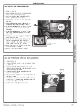
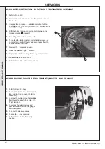
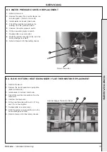
Remove the burner manifold and inspect the electrodes and
sightglass. Refer to Frames 54 and 61.
7.
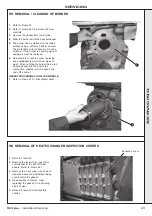
Remove and clean the burner. Refer to Frame 55.
8.
Inspect the heat exchanger through the burner opening.
Optionally remove the inspection covers on the left hand side
of the heat exchanger. If there are signs of aluminium oxide
build up, spray water down the flueways taking care not to
get water on the gas valve and controls. Refer to Frame 56.
9.
Remove the sump cover and scrape out any deposits. Refer
to Frame 57.
10.
Clean the condensate trap. Refer to Frame 58.
11.
Check that the flue terminal and air inlet are unobstructed
and that the fluing and ducting are correctly sealed.
REPEAT PROCEDURE FOR BOTH SLAVE AND MASTER
MODULES.
12.
After servicing refer to Frame 49 for final safety checks.
SER
VICING
Содержание F400
Страница 57: ...57 xtra Installation Servicing NOTES...
Страница 58: ...58 xtra Installation Servicing NOTES...
Страница 59: ...59 xtra Installation Servicing NOTES...

