4
and pull the module out.
4.
Installation of Control Module
1. Mount the control module into the case by secure-
ing it behind the mounting clips on both sides of
the case.
2. Reconnect the Molex connectors to proper posi-
tion. Each connector is designed to fit only in its re-
spective mating connector. If the plug is equipped
with a locking clip, ensure the clip is engaged.
3. Place the cover in place and lock in the top retain-
ing tab.
4. Remount the front jacket panel to the boiler.
5. Turn power to the unit “ON” and return the boiler
to service.
5. Replace Display Module
1. Pull the retaining clip on top of the enclosure and
pull the front cover off.
2. Disconnect the yellow cables by squeezing the clip
on the back of the plug in and pulling firmly out
from the back of the display module. Use care not
to damage the plug.
3. Remove the rubber grommet holdind the yellow
cables from the old display ensloure.
4. Install the rubber grommet with the yellow cables
onto one of the tabs in the bottom of the new dis-
play ensloure.
5. Reconnect the yellow cables by pushing the plug
into the terminal. The clip on the back of the plug
will lock the plug into place. Use care not to dam-
age the cable or display module.
6. Close the front cover onto the back cover by
insert-ing the two tabs on the bottom of the front
cover into the appriopriate holes in the back cover
and close, engaging the tab in the top. Give the
cover a light tug to make sure the top retaining
clip is tight.
Exalt
Control
& Display
Module Replacement
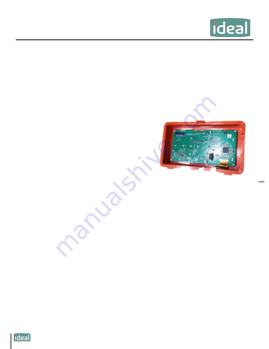
Fig.
9
: Display Module
The display module comes preinstalled in the front red dis-
play enclosure as shown in Fig. 8.
NOTICE


