background image

5

Concord Super Series 4 - 

Installation & Servicing

TECHNICAL DATA

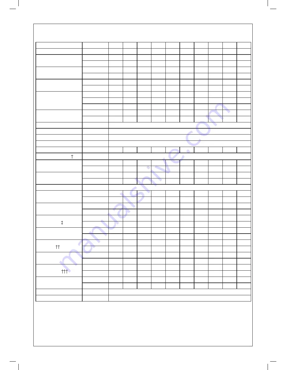
Table 2

Boiler

350 V 400 V 450 V 500 V 550 V 600 V 450 H 500 H 550 H 600 H

No. of modules

7

8

9

10

11

12

9

10

11

12

Heat output

kW

350

400

450

500

550

600

450

500

550

600

Btu/h x 10

3

1194

1365

1535

1706

1877

2047

1535

1706

1877

2047

Heat input

kW

411.6

470.4

592.2

588.0

646.8

705.6

529.2

588.0

646.8

705.6

Btu/h x 10

3

1404

1605

1806

2006

2207

2407

1806

2006

2207

2407

Gas rate

m

3

/h

38.6

44.1

49.7

55.2

60.7

66.2

49.7

55.2

60.7

66.2

ft.

3

/h

1363

1557

1752

1947

2143

2336

1752

1947

2143

2336

Flue gas mass 

volume * 

at 120ºC (248ºF)

g/s

175

200

225

250

275

300

225

250

275

300

l/s

191

219

246

273

301

328

246

273

301

328

ft.

3

/min

406

464

522

580

638

696

522

580

638

696

Required water

flow rate ± 10%

l/s

7.49

8.56

9.63

10.70

11.77

12.84

9.63

10.70

11.77

12.84

gal./min.

98.7

112.8

126.9

141.0

155.1

169.2

126.9

141.0

155.1

169.2

Hydraulic resistance

12.5 kN/m

2

 (50 in w.g.)

Maximum static head**

2 m (6.5 ft.)

Maximum static head

60.0 m (197 ft.)    6.0 bar (85 lb/in

2

)

Electricity supply

230 V ~ 50Hz,

Power consumption

W

630

720

810

900

990

1080

810

900

990

1080

Gas supply pressure 

20.0 mbar (8 in. w.g.)

Boiler height

(overall)

mm

1618

1618

2144

2144

2144

2144

1467

1467

1467

1467

in.

63.7

63.7

84.4

84.4

84.4

84.4

57.8

57.8

57.8

57.8

Boiler width

(overall)

m m

1822

1822

1833

1833

1833

1833

2393

2393

2393

2393

in.

71.7

71.7

72.2

72.2

72.2

72.2

94.2

94.2

94.2

94.2

Boiler depth (overall)

1350 mm (53.1 in.)

Weight of casing

and insulation

kg.

134

126

197

190

182

175

197

190

182

175

lb.

295

278

435

418

402

386

435

418

402

386

Weight of 

modules

kg.

371

424

477

530

583

636

477

530

583

636

lb.

818

935

1052

1168

1282

1402

1052

1168

1282

1402

Weight of gas &

water headers 

kg.

260

263

311

313

315

318

298

300

302

304

lb.

573

580

686

690

694

701

657

661

665

670

Water content

boiler

l.

63.3

68.1

97.6

102.4

107.2

112

92.6

97.4

102.2

107

gal.

14.1

15.1

21.6

22.7

23.9

24.9

20.5

21.6

22.7

23.7

Flow and return

connection 

mm

100

100

125

125

125

125

125

125

125

125

in.

4.0

4.0

5.0

5.0

5.0

5.0

5.0

5.0

5.0

5.0

Gas connection

Rc

2

2

2

2

2

2

2

2

2

2

in. BSP

2

2

2

2

2

2

2

2

2

2

Flue pipe size

(nominal bore) 

mm

350

350

400

400

450

450

400

400

450

450

in.

14

14

16

16

18

18

16

16

18

18

Flue socket size

mm

400

400

450

450

501

501

450

450

501

501

in.

15 

3

/

4

15 

3

/

4

17 

1

/

4

17 

1

/

4

19 

3

/

4

19 

3

/

4

17 

3

/

4

17 

3

/

4

19 

3

/

4

19 

3

/

4

Injector size

7.3 mm (0.28 in.)

Type of gas

Natural gas (G20 only)

GENERAL

Содержание Concord Super Series 4 100 V

Страница 1: ...d conform to the safety and performance specification that we require Do not use reconditioned or copy parts that have not been clearly authorised by Ideal For the very latest copy of literature for specification and maintenance practices visit our website www idealcommercialboilers com where you can download the relevant information in PDF format July 2018 UIN 100920 A12 ...

Страница 2: ......

Страница 3: ... Super Series 4 350 V 41 429 85 Concord Super Series 4 100 V 41 429 79 Concord Super Series 4 400 V 41 429 86 Concord Super Series 4 150 V 41 429 80 Concord Super Series 4 450 V 41 429 87 Concord Super Series 4 150 VA 41 429 81 Concord Super Series 4 500 V 41 429 88 Concord Super Series 4 200 V 41 429 82 Concord Super Series 4 550 v 41 429 89 Concord Super Series 4 250 V 41 429 83 Concord Super Se...

Страница 4: ...IREMENTS IMPORTANT GAS SAFETY INSTALLATION AND USE REGULATIONS 1994 All gas appliances must by law be installed by competent persons e g Gas Safe Registered Engineer in accordance with the above regulations Failure to install appliances correctly could lead to prosecution It is in your own interest and that of safety to ensure that the law is complied with In addition the installation must comply ...

Страница 5: ...sembly MODE OF OPERATION The normal mode of operation of the boiler is preceded in certain conditions by a period in which the complete boiler casing is given a three volume air change The air change is an important safety feature of the European requirements with which the boiler is designed to comply The air change will occur whenever the boiler goes form a situation of no modules firing to a si...

Страница 6: ... 7 37 1 37 6 56 1 56 7 56 7 56 1 71 5 71 5 Boiler depth overall 698 mm 27 4 in Weight of casing and insulation kg 29 1 47 7 61 5 76 6 106 6 98 9 84 0 107 0 99 0 lb 64 1 105 2 135 5 168 8 235 0 218 0 185 0 235 0 218 0 Weight of modules kg 53 106 159 212 265 318 159 212 318 lb 116 232 348 464 580 696 348 580 696 Weight of gas water headers kg 34 0 53 6 59 4 89 4 94 3 53 4 92 2 96 7 lb 75 118 131 197...

Страница 7: ...1080 Gas supply pressure 20 0 mbar 8 in w g Boiler height overall mm 1618 1618 2144 2144 2144 2144 1467 1467 1467 1467 in 63 7 63 7 84 4 84 4 84 4 84 4 57 8 57 8 57 8 57 8 Boiler width overall m m 1822 1822 1833 1833 1833 1833 2393 2393 2393 2393 in 71 7 71 7 72 2 72 2 72 2 72 2 94 2 94 2 94 2 94 2 Boiler depth overall 1350 mm 53 1 in Weight of casing and insulation kg 134 126 197 190 182 175 197 ...

Страница 8: ...llowed to enter the boiler house or adjacent buildings 7 Refer also to BS 6644 and to IGE UP 10 Installation of Gas Appliances in Industrial and Commercial Premises and IM 22 for further guidance AIR SUPPLY Detailed recommendations for air supply are given in BS 5440 2 and BS 6644 which MUST be consulted before proceeding Contamination of the air supply from any external source must be avoided wit...

Страница 9: ... the boiler casing To achieve the minimum neutral draught condition a vertical flue length of 2 metres is needed plus whatever extra height is necessary to overcome the resistance of any bend or duct work between the boiler casing and the vertical flue Note Air intake and discharge should be on the same outside wall face Design must comply with British Gas requirements refer page 5 and Publication...

Страница 10: ...8 Concord Super Series 4 Installation Servicing 5 BOILER DIMENSIONS 50KW 150KW MODELS All dimensions in millimetres inches GENERAL ...

Страница 11: ...9 Concord Super Series 4 Installation Servicing 6 BOILER DIMENSIONS 200KW 300KW MODELS All dimensions in millimetres inches GENERAL ...

Страница 12: ...10 Concord Super Series 4 Installation Servicing 7 BOILER DIMENSIONS 350KW 600KW MODELS All dimensions in millimetres inches GENERAL ...

Страница 13: ...ple 10 Flow and return spools 11 Rc1 1 2 elbow 12 Space nipple 13 Short space nipple 14 Main gas cock not shown 15 Rc 2 twin elbow with two hex bushes 16 1 1 2 M F elbow 17 Return manifold short Note 1 To aid the assembly procedure on the flow return manifolds and the flow return spools the flanges are left loose for site welding 2 The double M F elbows 12 are to enable ease of fit and squareness ...

Страница 14: ...ct volume flow rate given above the hydraulic resistance of all Ideal Concord Super boilers is 12 5 kN m2 50 in w g Pump Over run A pump over run time of 30 seconds minimum must be allowed for on plant shutdown Maximum Static Head 60m 197 ft i e maximum operating pressure 6 0 bar 85 lb in2 Minimum Static Head Minimum static head requirements for open vented systems must comply with boiler design c...

Страница 15: ...eader must be sized at least one pipe size larger than the boiler flow and return manifold size This will avoid hydraulic interference between the boiler primary pump and system zone pumps The use of a mixing header means that compensating controls can be used to operate mixing valves on a variable temperature circuit without affecting the water flow rate through the boiler 10 GUIDE TO MINIMUM REQ...

Страница 16: ... system water expands into the tank as the system heats up Conversely as the system cools water is drawn back from the tank into the system together with a quantity of dissolved oxygen Also there will be evaporation losses from the surface of the tank which depending on ambient temperature maybe high enough to evaporate a large portion of the system water capacity over a full heating season For th...

Страница 17: ...W Two wiring centres as shown in Frame 12 are supplied fitted one each side of the boiler case It is important to ensure that the electrical wiring takes this factor into account Each wiring centre can accommodate up to six modules GENERAL LEGEND PCB Printed Circuit Board b blue bk black br brown r red y yellow w white g y green yellow or orange v violet pk pink ...

Страница 18: ...16 Concord Super Series 4 Installation Servicing LEGEND br brown b blue r red g grey v violet pk pink y yellow w white or orange bk black g y green yellow 13 50KW MODULE WIRING GENERAL ...

Страница 19: ...of the bellows to tighten in position When tight the flange on the bellows should finish approximately 470 mm 181 2 in away from the fixed flanges with the flange holes in a vertical and horizontal attitude refer to Frame 14 UNDER NO CIRCUMSTANCES MUST THE FLANGE OR BELLOWS BE USED FOR TIGHTENING 3 Secure the flow and return water headers to the modules rigid flanges first using the gaskets and sc...

Страница 20: ... the boiler 6 0 bar 85 lb in2 ELECTRICAL CONNECTIONS Refer Frames 12 13 a Each module Undo the two M4 screws on the right hand side of the control box and swing the front control panel out b 50kw single module boiler only Fit the prewired low voltage 10 way plug supplied in the hardware pack into the socket at the top RH corner of Board No 28 Note that it will fit only one way round with the clip ...

Страница 21: ...AIN ASSEMBLY DETAIL OF GAS HEADER FLEXIBLE HOSES LEGEND 1 Flue sampling point 2 Wiring centre 3 Water header 4 Gas pressure test point 5 50kW module 6 Module cover Note M12 flange bolts must be fitted pointing away from the module for the outer connections and pointing towards the module for the inner connections ASSEMBLY ...

Страница 22: ...cork gasket 6A Burner fibre gasket 7 Flow header 8 Flow header gasket 9 Burner 10 Top cover plate 11 Cover plate gasket 12 Top tube plate 13 Gas distribution screen 14 Finned copper tubes 15 Bottom tube plate 16 Cover plate gasket 17 Bottom cover plate 18 Sight glass 19 Flame sensor 20 Return header gasket 21 Return header 22 Gas air control 23 Gas valve 24 Fan assy 25 Thermostat pocket Note Items...

Страница 23: ...trol 7 Gas inlet pressure test point 8 Gas valve 9 4mm sensing line Note Items 6 8 supplied as an assembly LEGEND 1 LED s 2 Lockout reset button 3 PCB No 28 4 Safety temperature limiter 5 Mains socket 6 Fan motor 7 Fan impellor 8 Fan scroll 8a Fan gasket 9 Flame sensing lead 10 Ignition lead 11 PCB No 29 12 On Off switch 13 Thermostat knob 16 ELECTRICAL CONTROLS Exploded View 17 GAS LINE ASSEMBLY ...

Страница 24: ...f the module gas service tap and continue with the next module Pre firing check refer Frames 15 16 17 18 Ensure that a The electrical supply to the boiler is OFF b The orange covers are removed c The black mains plugs on the left side of each module are removed Note EXTREME CARE SHOULD BE TAKEN WHEN THE MODULE IS RUN WITHOUT A COVER Each module should be checked as follows 1 Switch the module on o...

Страница 25: ...e following sequence of events should occur a The mains ON light will illuminate b For multi module boilers The fan will start and run for approximately 30 seconds part 3 of the volume air change safety feature then stop for 1 50 seconds depending upon the modules position in the switching sequence It will then re start and run for approximately 15 seconds For single module boilers The fan will st...

Страница 26: ...int is provided in the top of the boiler casing adjacent to the flue outlet socket Frame 14 For DRAEGAR tests note the following a The sampling line however short should ALWAYS be purged b CO2 tubes are marked in per cent divisions and ONE pump only is required CO tubes are also marked in divisions indicating parts per million p p m c The ratio CO CO2 should not exceed 0 001 For convenient referen...

Страница 27: ... H Front 450 VH Rear B B 1 2 2 3 4 4 6 B 1 2 2 3 4 B 4 6 B 1 2 2 3 4 4 6 5 8 500 VH Front Rear B 1 2 2 3 4 4 6 5 8 B 1 2 2 3 4 4 6 5 8 550 VH Front Rear B 1 2 3 4 5 1 2 3 4 5 6 600 VH Front Rear 1 2 3 4 5 6 1 2 3 4 5 6 Module No refer Frames 5 6 7 6 5 4 3 2 1 B denotes blank Note Due to the different starting characteristics built into individual wiring centres modules set at the same control posi...

Страница 28: ...sing line union connections at the square to round casting and at the gas air control unit and remove the sensing line 9 Undo the 6 mm pressure sensing line union connections at the fan housing base and at the gas air control unit and remove the sensing line 10 Undo the 3 elongated M8 nuts with slotted heads securing the fan assembly 11 Remove the fan assembly taking care not to damage the fan imp...

Страница 29: ...ket connection 7 Remake the fan motor plug and socket connection 8 Secure the fan motor lead and mains harness lead in the clip on the left hand underside of the fan plate 9 Pass the ignition lead through the cable tie wrapped round the return elbow behind the gas valve 10 Remake the ignition electrode connection 11 Secure the control panel with the M5 screw 12 Remake the multi pin plug connection...

Страница 30: ...ty temperature limiter sensors from their pockets 14 Unscrew the two M5 x 10mm lg pozi screws securing the control panel support bracket to the angle bracket and remove the control panel assembly 15 Unscrew the four M10 nuts securing the module to the casing and withdraw the module 16 Unscrew the screws holding the gas distribution screen over the finned tubes and remove the screen The module heat...

Страница 31: ...paring the boiler 1 Unscrew the two retaining screws from the front of the orange cover and remove the cover 2 Withdraw the multi pin plug from the left hand side of the module and switch off the module on off switch 3 Unscrew the two M4 screws at the right hand edge of the control panel and open the front control panel door refer Frame 19 4 Unplug the low voltage 10 way plug from the top right ha...

Страница 32: ...el door and withdraw the lead 3 Fit the replacement probe in reverse order Boiler Adjustable Control Thermostat Potentiometer 1 Unplug the potentiometer lead from the printed circuit board No 28 behind the front control panel door 2 Loosen the retaining screw of the thermostat control knob on the right hand side of the fascia and pull off the knob 3 Undo the hexagon nut securing the potentiometer ...

Страница 33: ...eteriorating gaskets 3 Fit the replacement fan assembly in reverse order 4 The module MUST now be recommissioned with particular reference to measuring the differential air pressure Refer to Commissioning and Testing pages 22 25 Gas Valve Gas air Control Unit Assembly WARNING This assembly is supplied only as a complete service unit and changed as such do not separate The factory fitted 4mm pipes ...

Страница 34: ...er to removal renewing any damaged or deteriorated gaskets as necessary Module Cover Fitter 1 Unscrew the M5 nut on each side of the cover then prise open the edge clips and release the wire frame of the filter see Frame 29 2 Fit the replacement filter in reverse order Wiring Centre Board No 30 1 Unscrew the four screws securing the wiring centre cover and remove the cover 2 Disconnect the mains s...

Страница 35: ...ard PCB No 29 1 100 647 19 Module cover assembly Vertical 1 100 823 20 Module cover filter 1 100 619 21 Printed circuit board PCB No 30 1 100 648 22 Module flange gaskets 2 012 745 23 Module top cover plate gasket 1 100 936 24 Module bottom cover plate gasket 1 100 935 25 Module cover assembly Horizontal 1 100 824 26 Header gaskets triangular 2 012 593 27 Gas distribution screen aluminium wrapper ...

Страница 36: ...o 28 Does fan start Fit a new fan Is there mains voltage to the fan Fit new safety temperature limiter Fit new module sensor Reset safety temperature limiter Does overheat light go out Fit a new Board No 30 Are any mains lights off Are module on off switches operating Fit new Board No 30 Fit a new Board No 28 Is mains light on Are Board No 30 fuses intact Are all electrical connections made Is loc...

Страница 37: ... air filters fan impellor heat exchanger flues burner Set burner gas pressure to 6 8 mbar Does the burner light Are the gas cocks open Do the gas valves open Is there mains voltage to the gas valve Fit a new gas valve gas air control unit Does the burner remain alight When firing is the minimum inlet gas pres sure 15mb measured at the gas header point Is the detection lead and probe OK Fit a new B...

Страница 38: ...s seconds Btu h kW 3 Combustion data measured at sampling point at top of boiler See Table 3 i CO ii CO2 iii CO CO2 4 Fan pressure differential Note 1 in w g mbar 1 BOILER MODEL see data plate Please tick appropriate box 50v 100v 150v 150va 200v 250v 300v 250h 300h 350v 400v 450v 500v 550v 600v 450h 500h 550h 600h Note 1 Delete units as appropriate Note 2 CV is 1031 Btu cubic ft if volume is measu...

Страница 39: ...37 Concord Super Series 4 Installation Servicing ...

Страница 40: ...32 Ideal is a trademark of Ideal Boilers Registered Office Ideal Boilers Ltd PO Box 103 National Avenue Kingston Upon Hull HU5 4JN Tel 01482 492251 Fax 01482 448858 Registration No London 322 137 Ideal Technical Helpline 01482 498376 www idealcommercialboilers com Ideal Boilers Ltd pursues a policy of continuing improvement in the design and performance of its products The right is therefore reser...

Отзывы: