manualshive.com logo in svg
background image

Manual Number: 00750-004-14

Page 2-1

Chapter 2: Address Selection

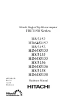
Each serial port on the WINCOMM4 board occupies 8 consecutive I/O locations.  A dip switch is
used to set the base address for these locations.  Be careful when selecting the base address as some
selections conflict with existing PC ports.  The following table shows several examples that usually
do not cause a conflict.

SW 4 sets the I/O address for port 1, SW 3 sets the address for port 2, SW 2 sets the I/O address for
port 3, SW 1 sets the address for port 4, as labeled on the cable.

s

s

e

r

d

d

A

y

r

a

n

i

B

s

g

n

i

t

t

e

S

n

o

i

t

i

s

o

P

h

c

t

i

w

S

9

A

0

A

1

2

3

4

5

6

7

7

8

2

-

0

8

2


0

0

0

1

0

1

X

X

X

0

F

F

O

N

O

F

F

O

N

O

N

O

N

O

N

O

7

A

2

-

0

A

2


0

1

0

1

0

1

X

X

X

0

F

F

O

N

O

F

F

O

N

O

F

F

O

N

O

N

O

:

2

M

O

C

F

F

2

-

8

F

2

1

1

1

1

0

1

X

X

X

1

F

F

O

N

O

F

F

O

F

F

O

F

F

O

F

F

O

F

F

O

:

1

M

O

C

F

F

3

-

8

F

3

1

1

1

1

1

1

X

X

X

1

F

F

O

F

F

O

F

F

O

F

F

O

F

F

O

F

F

O

F

F

O

:

4

M

O

C

F

E

2

-

8

E

2

0

1

1

1

0

1

X

X

X

1

F

F

O

N

O

F

F

O

F

F

O

F

F

O

N

O

F

F

O

:

3

M

O

C

F

E

3

-

8

E

3

0

1

1

1

1

1

X

X

X

1

F

F

O

F

F

O

F

F

O

F

F

O

F

F

O

N

O

F

F

O

7

2

3

-

0

2

3


0

1

0

0

1

1

X

X

X

0

F

F

O

F

F

O

N

O

N

O

F

F

O

N

O

N

O

F

2

3

-

8

2

3

0

1

0

0

1

1

X

X

X

1

F

F

O

F

F

O

N

O

N

O

F

F

O

N

O

F

F

O

If you don’t see an address in the table that is compatible with your software, you can determine the
switch setting for a particular address by using the table below.  The following table shows the
correlation between the dip switch setting and the address bits used to determine the base address.  In
the example below, the address 300 HEX through 307 HEX is selected.  300 HEX = 11  0000  0XXX
in binary representation.

Содержание WINCOMM4

Страница 1: ...Model WINCOMM4 Product Manual MANUAL NUMBER 00750 004 14C...

Страница 2: ...ual in our online Support Library Thank you The information in this document is provided for reference only ICS Advent does not assume any liability arising from the application or use of the informat...

Страница 3: ...ts which are not in an as new and re saleable condition are not eligible for credit return and will be returned to the customer Limited Warranty Effective April 1 1998 all products carry a 2 year limi...

Страница 4: ...made by various manufacturers in performing warranty repairs and building replacement products If ICS Advent repairs or replaces a product its warranty term is not extended ICSAdvent will normally ret...

Страница 5: ...Cautions and Warnings are accented with triangular symbols The exclamation symbol is used in all cautions and warnings to help alert you to the important instructions The lightning flash symbol is us...

Страница 6: ...lection 3 1 Port Enable Disable 3 1 Chapter 4 Technical Description 4 1 WINCOMM4 Four Port RS 232 Serial Interface 4 1 Features 4 1 How to remain CE Compliant 4 1 Chapter 5 Specifications 5 1 Declarat...

Страница 7: ...ts except J8 on the original IBM XT and portable Be sure to set the address and jumper options before installation Remove the PC case remove the blank metal slot cover and insert the board Replace the...

Страница 8: ...CD 29 P2 6 DSR 30 P2 4 RTS 31 P2 5 CTS 32 P2 22 RI 33 P1 7 GND 34 P1 20 DTR 35 P1 2 TD 36 P1 3 RD 37 P1 8 DCD DB 25 PORT 1 PORT 4 PINOUTS SIGNAL NAME PINOUT MODE TD TRANSMIT DATA 2 OUTPUTRS 232 RTS RE...

Страница 9: ...0 1 0 1 X X X 0 F F O N O F F O N O F F O N O N O 2 M O C F F 2 8 F 2 1 1 1 1 0 1 X X X 1 F F O N O F F O F F O F F O F F O F F O 1 M O C F F 3 8 F 3 1 1 1 1 1 1 X X X 1 F F O F F O F F O F F O F F O...

Страница 10: ...Position Address Line Example 300 Hex Switch 1 A9 1 OFF 2 A8 1 OFF 3 A7 0 ON 4 A6 0 ON 5 A5 0 ON 6 A4 0 ON 7 A3 0 ON Note that setting the switch ON or CLOSED corresponds to a 0 in the address while...

Страница 11: ...tting If COM2 is selected this jumper must be on IRQ3 NOTE Most communications software applications default COM3 to IRQ4 and COM4 to IRQ3 This requires the sharing of interrupts between COM1 and COM3...

Страница 12: ...ows more than one port to access a single IRQ The M indicates the inclusion of a 1K OHM pull down resistor required on one port when sharing interrupts E5 M M S S N N Set the jumpers to N for single i...

Страница 13: ...if you are using more than one WINCOMM4 in a BUS or you wish to completely remove the pull down resistor for hardware compatibility Setting the board in this configuration when it is not accompanied b...

Страница 14: ...ake signals such as CTS or DCD Consult the particular manual for your software to determine these requirements If none are mentioned or if you are not sure a safe configuration is to tie DTR to DSR an...

Страница 15: ...Range 0 90 R H Non Conddensing 0 90 Non Condensing Performance MTBF 150 000 Hours Manufacturing IPC 610 A Class III standards adhered to with 0 1 visual A Q L and 100 Functional Testing Boards are bu...

Страница 16: ...munity EN61000 4 3 1995RadiatedRFFieldImmunity EN61000 4 4 1995EFTImmunityforACandI OLines EN 60950 1992 Safety of InformationTechnology Equipment Thetechnicaldocumentationrequiredtodemonstratethispro...

Отзывы: