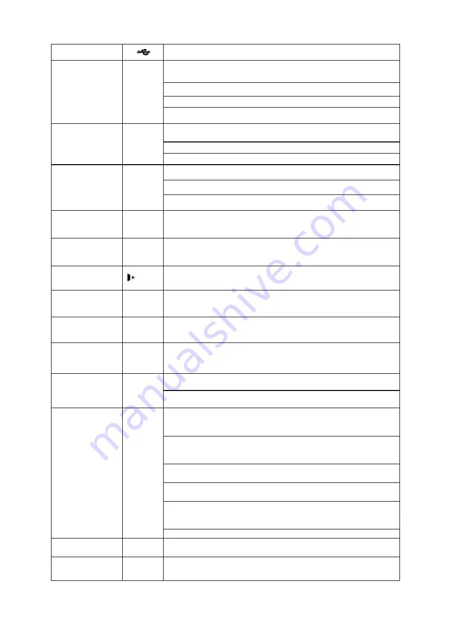
background image


USB port 


To connect USB storage device, USB mouse. 
 

Up/ 
Down 


Activate  current  control,  modify  setup,  and  then  move  up 
and down. 
 

Increase/decrease numeral. 


Assistant function such as PTZ menu. 

Input number 1/4. 

Left/ 
Right 


Shift current activated control, and then move left and right. 

When playback, click these buttons to control playback bar. 

Input number 2/3. 

Enter 

ENTER 

Confirm current operation 

Go to default button 

Go to menu  

Reverse/Pau
se 


In  normal  playback  or  pause  mode,  click  this  button  to 
reverse Playback 
Input number 5. 
 
In reverse playback, click this button to pause playback. 
Input number 5. 

Play/Pause  


In normal playback click this button to pause playback 
In pause mode, click this button to resume playback. 
Input number 6. 

Slow play 


Multiple slow play speeds or normal playback. 
Input number 8. 

Fast play 


Various fast speeds and normal playback. 
Input number 7. 

Play previous 

I


In playback mode, playback the previous video. 
Input number 9. 

Play Next 

I


In playback mode, playback the next video 
Input number 0. 

ESC 

ESC 

Go to previous menu, or cancel current operation. 

When playback, click it to restore real-time monitor mode.  

Assistant 

Fn 

One-window  monitor  mode,  click  this  button  to  display 
assistant function: PTZ control and image color. 
 
Backspace function: in numeral control or text control, press 
it for 1.5 seconds to delete the previous character before the 
cursor. 
In  motion  detection  setup,  working  with  Fn  and  direction 
keys to realize setup. 
In  text  mode,  click  it  to  switch  between  numeral,  English 
character(small/capitalized) and etc. 
In  HDD  management  interface,  you  can  click  it  to  switch 
HDD  record  information  and  other  information  (Menu 
prompt) 
Realize other special functions. 

Shift 


In  textbox,  click  this  button  to  switch  between  numeral, 
English(Small/Capitalized),donation and etc. 

Record 

REC 

Manually stop/start recording, working with direction keys  
or numeral keys to select the recording channel. 

Содержание N6 CIF Series

Страница 1: ...N6 CIF Series Standalone DVR Quick Start Guide Version 1 0 1 ...

Страница 2: ...1 8 Alarm Input and Output Connection 9 1 8 1 Alarm Input and Output Details 9 1 8 2 Alarm Input Port 11 1 8 3 Alarm Output Port 11 2 Overview of Navigation and Controls 12 2 1 Login Logout Main Menu 12 2 1 1 Login 12 2 1 2 Main Menu 13 2 1 3 Logout 13 2 1 4 Auto Resume after Power Failure 14 2 2 Live Viewing 14 2 3 Manual Record 15 2 3 1 Manual record menu 15 2 3 2 Basic operation 15 2 3 3 Enable...

Страница 3: ...rity 25 2 6 4 Image FTP 25 2 7 Network 25 2 7 1 Network Setting 27 2 8 Pan Tilt Zoom 28 2 8 1 PTZ Setup 28 2 8 2 PTZ Operation 29 2 8 3 3D Intelligent Positioning Key 30 3 Web Client Operation 31 3 1 Network Connection 31 3 2 Login 31 3 3 Main Window 32 3 3 1 LAN Login 32 3 3 2 WAN Login 32 Appendix Toxic or Hazardous Materials or Elements 33 ...

Страница 4: ...pwards Handle with care Do not apply power to the DVR before completing installation Do not place objects on the DVR 4 Qualified engineers needed All the examination and repair work should be done by the qualified service engineers We are not liable for any problems caused by unauthorized modifications or attempted repair 5 Environment The DVR should be installed in a cool dry place away from dire...

Страница 5: ...ion keys in the front panel and the ports in the rear panel please refer to the User s Manual included in the resource CD The model label in the front panel is very important please check according to your purchase order The label in the rear panel is very important too Usually we need you to represent the serial number when we provide the service after sales 1 3 After Remove the Chassis Please ch...

Страница 6: ...1 1 Please refer to the following sheet for front panel button information Name Icon Function Power button Power button press this button for three seconds to boot up or shut down DVR 5 Use screws to fix HDD 6 Install the upper bracket and then Use screws to fix HDD in the bracket 7 Unfasten the HDD power cable 9 Use the special data cable to connect the HDD and the SATA port Close the chassis and...

Страница 7: ...put number 7 Play previous I In playback mode playback the previous video Input number 9 Play Next I In playback mode playback the next video Input number 0 ESC ESC Go to previous menu or cancel current operation When playback click it to restore real time monitor mode Assistant Fn One window monitor mode click this button to display assistant function PTZ control and image color Backspace functio...

Страница 8: ...sheet for front panel button information Name Icon Function Power button Power button press this button for three seconds to boot up or shut down DVR Number and Character 0 In text mode input number 0 It is the space button 1 In text mode input number 1 and denotation 2ABC In text mode input number 2 English character A B C 3DEF In text mode input number 3 English character D E F 4GHI In text mode...

Страница 9: ...n keys or numeral keys to select the recording channel Window switch Mult Click it to switch one window multiple window Slow play 8 Multiple slow play speeds or normal playback Assistant Fn One window monitor mode click this button to display assistant function PTZ control and image color Backspace function in numeral control or text control press it for 1 5seconds to delete the previous character...

Страница 10: ...te control indication light Power indication light Power Power indication light Record light 1 16 System is recording or not It becomes on when system is recording For this series product the last 12 lights are null since there is only four channels IR Receiver IR It is to receive the signal from the remote control Shuttle outer ring In real time monitor mode it works as left right direction key P...

Страница 11: ...Video output 11 Audio Bidirectional talk output port 12 Bidirectional talk input port 13 Power on off button 14 GND port 1 6 2 2U series This series DVR rear panel is shown as below See Figure 1 4 Please note the following figure is based on the 24 32 channel series product Figure 1 4 Please refer to the following sheet for detailed information 1 GND port 2 Power input port 3 Power button 4 Fan 5 ...

Страница 12: ...ut Alarm output RS485 port 14 Network port 15 HDMI port 16 RS232 port 17 eSATA port 18 USB port 19 Video VGA output When connect the Ethernet port please use crossover cable to connect the PC and use the straight cable to connect to the switcher or router 1 7 Connection Sample Please refer to Figure 1 5 for connection sample Please note the following figure is based on the 32 channel 2U series pro...

Страница 13: ...specifications for the alarm input and output channel amount Do not merely count the alarm input and out channel amount according to the ports on the rear panel There are two alarm input types for you to select normal open NO and normal close NC 1 8 1 Alarm Input and Output Details ...

Страница 14: ...rface is shown as in Figure 1 7 Figure 1 7 You can refer to the following sheet and Figure 1 7 for alarm input and output information 1 2 3 4 5 6 7 8 9 10 11 12 13 14 15 16 ALARM 1 to ALARM 16 The alarm becomes active in low voltage NO1 C1 NO2 C2 NO3 C3 NO4 C4 NO5 C5 NC5 The first four are four groups of normal open activation output on off button NO5 C5 NC5 is a group of NO NC activation output o...

Страница 15: ...alarm detector Provide external power to the alarm detector Please parallel connect the Ground of the DVR and the ground of the alarm detector Please connect the NC port of the alarm sensor to the DVR alarm input ALAR M Use the same ground with that of DVR if you use external power to the alarm device Figure 1 8 1 8 3 Alarm Output Port Provide external power to external alarm device To avoid overl...

Страница 16: ...ormation See Figure 2 1 Figure 2 1 The system login interface is shown as in Figure 2 2 System consists of four accounts Username admin Password admin administrator local and network Username 888888 Password 888888 administrator local only Username 666666 Passwords 666666 Lower authority user who can only monitor playback backup and etc Username default Password default hidden user You can use USB...

Страница 17: ...er the sub menu Figure 2 3 2 1 3 Logout There are two ways for you to log out The first one is from menu option In the main menu click shutdown button you can see an interface is shown as below See Figure 2 4 Figure 2 4 There are several options for you See Figure 2 5 Figure 2 5 The other ways is to press power button on the front panel for at least 3 seconds system will stop all operations Then y...

Страница 18: ...se to select any playback start time Support playback pause and exit function Right now system does not support slow playback and backward playback function Support digital zoom function Support real time backup function You can follow the contents listed below for the operation instruction Preview control interface Move you mouse to the top centre of the video of current channel you can see syste...

Страница 19: ... note the tour function has the higher priority than the preview playback System automatically exits the preview playback function and its corresponding interface when the tour function started You can not control the preview playback until the tour function ended 2 3 Manual Record Note You need to have proper rights to implement the following operations Please make sure the HDD has been properly ...

Страница 20: ...ht channel number See Figure 2 8 Figure 2 8 2 3 4 Enable all channel recording Highlight below All you can enable all channel recording All channel schedule record Please highlight ALL after Schedule See Figure 2 9 When system is in schedule recording all channels will record as you have previously set Main menu Setting Schedule The corresponding indication light in front panel will turn on ...

Страница 21: ...ins manual record now Figure 2 10 2 3 5 Stop all channel recording Please highlight ALL after Stop See Figure 2 11 System stops all channel recording no matter what mode you have set in the menu Main menu Setting Schedule Figure 2 11 2 4 Search Playback Click search button in the main menu search interface is shown as below See Figure 2 12 Usually there are three file types R Regular recording fil...

Страница 22: ...indow playback mode you can select 1 16 channels In 4 window playback mode you can select 4 channels according to your requirement In 9 window playback mode you can switch between 1 9 and 10 16 channels In 16 window playback mode you can switch between1 16 and 17 32 channels The time bar will change once you modify the playback mode or the channel option 5 File list switch button Double click it y...

Страница 23: ...use current play In backward play mode click to restore normal play In playback mode click it to play the next or the previous section You can click continuously when you are watching the files from the same channel In normal play mode when you pause current play you can click and to begin frame by frame playback In frame by frame playback mode click to restore normal playback Slow play In playbac...

Страница 24: ... in the time bar of the corresponding channel You can adjust the slide bar or input the accurate time to set the file end time Click this button again and then save current contents in a new file 12 Record type In any play mode the time bar will change once you modify the search type 13 Smart search Click the button system begins smart search System supports 396 22 18 PAL and 330 22 15 NTSC zones ...

Страница 25: ...anges from 1 to 30 seconds depending on the bit stream Redundancy System supports redundancy backup function You can highlight Redundancy button to activate this function Please note before enable this function please set at least one HDD as redundant Main menu Advanced HDD Management Please note this function is null if there is only one HDD Snapshoot You can enable this function to snapshoot ima...

Страница 26: ...le damage occurred in one disk there is a spare one in the other disk You can use this function to maintain data reliability and safety In the main menu from Setting to Schedule you can highlight redundancy button to enable this function See Figure 2 16 In the main menu from Advanced to HDD management you can set one or more disk s as redundant You can select from the dropdown list See Figure 2 16...

Страница 27: ...sk Main menu Advanced HDD management See Figure 2 16 System needs to reboot to get setup activated Now you can search or playback file in redundant disk Dismantle the disk and play it in another PC 2 6 Snapshot Please note the 24 32 channel series product supports 24 32 channel snapshot function 2 6 1 Schedule Snapshot In Encode interface click snapshot button to input snapshot mode size quality a...

Страница 28: ...de size quality and frequency See the interface on the left of Figure 2 18 In FTP interface please input upload interval See the interface in the middle of Figure 2 17 In Detect interface please enable snapshot function for specified channels interface in the middle of Figure 2 18 Or in alarm interface interface on the right of Figure 2 18 please enable snapshot function for specified channels Ple...

Страница 29: ...n Please enable FTP function and then click save button See Figure 2 19 Please boot up corresponding FTP server Please enable schedule snapshot Chapter 2 5 or activation snapshot Chapter 2 6 2 first now system can upload the image file to the FTP server Figure 2 19 2 7 Network Here is for you to input network information IP Version There are two options IPv4 Figure 2 20 and IPv6 Figure 2 21 Right ...

Страница 30: ... You need to disable DHCP function to view current IP information Besides when PPPoE is operating you can not modify IP Subnet mask Gateway TCP port Default value is 37777 You can change if necessary UDP port Default value is 37778 You can change if necessary HTTP port Default value is 80 RTSP port Default value is 554 Important System needs to reboot after you change d and saved any setup of the ...

Страница 31: ... Figure 2 21 2 7 1 Network Setting Network setting interface is shown as in Figure 2 22 Please check the box to enable corresponding function and then double click current item to go to setup interface Subnet Prefix ...

Страница 32: ...ease switch camera monitor channel to current window 2 8 1 PTZ Setup The pan tilt zoom setup includes the following items Please select channel first See Figure 2 23 Protocol Select corresponding PTZ protocol such as PELCOD Address Input corresponding PTZ address Baud rate Select baud rate Data bit Select data bit Default value is 8 Stop bit Select stop bit Default value is 1 Parity There are thre...

Страница 33: ...re 2 24 Figure 2 24 Click Pan Tilt Zoom the interface is shown as below See Figure 2 25 Here you can set the following items Step value ranges from 1 to 8 Zoom Focus Iris Click icon and to adjust zoom focus and iris Figure 2 25 In Figure 2 25 please click direction arrows See Figure 2 26 to adjust PTZ position There are total 8 direction arrows Please note if you use remote control you can use jus...

Страница 34: ...le screen mode Drag the mouse in the screen to adjust section size It can realize PTZ automatically Figure 2 27 Here is a sheet for you reference Name Function key function Shortcut key Function key function Shortcut Key Zoom Near Far Focus Near Far Iris close Open You can click set button in Figure 2 25 or click REC button in the front panel to set preset tour and pattern You can click page switc...

Страница 35: ...the control or you can go to C Program Files webrec to delete Single folder Current series product supports various browsers such as Safari firebox browser Google browser Device only support 1 channel monitor on the Apple PC 3 2 Login Open IE and input DVR address in the address column For example if your DVR IP is 10 10 3 16 then please input http 10 10 3 16 in IE address column System pops up wa...

Страница 36: ...See Figure 3 2 Click the channel name on the left side you can view the real time video Figure 3 2 3 3 2 WAN Login In WAN mode after you logged in the interface is shown as below See Figure 3 3 Figure 3 3 For detailed operation information please refer to the User s Manual included in the resources CD ...

Страница 37: ... or elements contained in products will not leak or mutate so that the use of these substances or elements will not result in any severe environmental pollution any bodily injury or damage to any assets The consumer is not authorized to process such kind of substances or elements please return to the corresponding local authorities to process according to your local government statutes Note For de...

Отзывы: