10
2.13.3 Air Conditioner (or Heat Pump)
An air conditioning coil may be installed on the supply air side
ONLY.
WARNING
Poisonous carbon monoxide gas hazard.
Install the evaporator coil on the supply side of the
furnace ducting ONLY.
An evaporator coil installed on the return air side of the
ducting can cause condensation to form inside the heat
exchanger, resulting in heat exchanger failure. This in
turn, can result in death, bodily injury and/or property
damage.
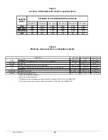
A clearance of 15 cm (6") is required between the bottom of
the coil drain pan and the top of the heat exchanger. If a heat
pump is installed, a “dual-energy” thermostat, or other control
is required, in order to prevent the simultaneous operation of
the furnace and the heat pump. It also prevents a direct
transition from heating by way of the heat pump to heating with
oil. Refer to the thermostat instructions or those of another
control used for the proper wiring.
If a coil blower compartment is used, install air tight, motorized
and automatic air dampers. Cold air coming from the coil and
passing across the furnace can cause condensation and
shorten the life of the heat exchanger.
3 OPERATION
3.1 START-UP
Before starting up the unit, be sure to check that the following
items are in compliance:
1.
The electrical installation, the oil supply system, the
venting system, combustion air supply and ventilation;
2.
The blower access door is in place and the blower rail
locking screws are well tightened;
3.
The Blocked Vent Shut-Off (BVSO) is installed according
to instructions (for chimney venting);
4.
The oil supply valve is open;
5.
The burner ‘’Reset’’ button is well pushed in or re-armed;
6.
The preliminary air adjustments on the burner comply with
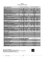
the technical specifications in this manual;
7.
The blower speed adjustments for heating and air
conditioning are appropriate and according to the
specifications in this manual;
8.
The blower start/stop delays are satisfactory;
9.
The thermostat of the room is in the heating mode and is
set higher than the ambient temperature.
To start the unit, turn the main electrical switch on.
3.2 OPERATING
SEQUENCE
OIL
HEATING
MODE
1.
The W-R contact closes;
2.
The burner motor starts up to pre-purge the
combustion chamber for a period of 10 to 15
seconds. During that time a spark is established on
the electrodes;
3.
The solenoid valve opens and a flame is established.
Shortly after, the electrodes cease to spark;
4.
Then the blower runs up to full speed. The delay
depends on the adjustments that were made on the
electronic board, which controls the blower motor.
Refer to Sections 2.11 and 2.12, p. 8 and 9 above, as
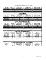
well as the CFM table for more details.
5.
When the call for heat is satisfied, the solenoid valve
closes, the flame goes out and the burner motor
stops (after post purge delay, if applicable).
6.
The blower stops shortly after the burner. The delay
depends on the adjustments that were made on the
electronic board that controls the blower. Refer to
Sections 2.11 and 2.12, p. 8 and 9 above, as well as
the CFM table for more details.
Note: A detailed operating sequence of the oil burner is
outlined in the instructions provided with the burner.
3.3 CHECKS
AND
ADJUSTMENTS
3.3.1
Purging the oil line
Open the bleed port screw and start the burner. Allow the
oil to drain into a container for at least 10 seconds. The oil
should flow absolutely free of white streaks or air bubbles
to indicate that no air is being drawn into the suction side
of the oil piping and pump. Slowly close and tighten the
bleed screw. Once closed, the flame will light up.
3.3.2 Pressure
adjustment
The oil pressure must be adjusted according to the
Technical Specifications of this manual. An adjustment
screw and a connection for a pressure gauge are located
on the oil pump for that purpose. Also refer to the burner
instruction manual.
445 01 4101 00
Содержание OMF112K14A
Страница 17: ...17 Figure 5 Furnace dimensions 445 01 4101 00...
Страница 18: ...18 Figure 6 Wiring Diagram 4 Speed Motor PSC 445 01 4101 00...
Страница 19: ...19 Figure 7 Wiring Diagram Variable Speed Motor ECM 445 01 4101 00...
Страница 20: ...20 PARTS LIST With 4 Speed motor PSC B50091B 445 01 4101 00...
Страница 22: ...22 PARTS LIST With variable speed motor ECM B50092B 445 01 4101 00...


