background image

SERVICE AND TECHNICAL SUPPORT MANUAL

Gas Furnace: N9MSB

Specifications  subject to change without notice.

440 04 4412 01

17

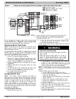
14. Reinstall 2 screws securing blower assembly to blower

deck.

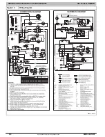
15. Reconnect blower leads to furnace control. Refer to

furnace wiring diagram, and connect thermostat leads if

previously disconnected.

NOTE

:  Be sure to attach ground wire and reconnect blower

harness plugs to blower motor.

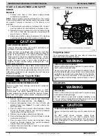
ELECTRICAL OPERATION HAZARD

Failure to follow this warning could result in personal

injury or death.
Blower door switch opens 115

V power to control. No

component operation can occur unless switch is closed.

Caution must be taken when manually closing this

switch for service purposes.

!

WARNING

16. Downflow or horizontal furnaces with vent pipe through

furnace only:
a. Install and connect short piece of vent pipe inside

furnace to existing vent.

b. Connect vent connector to vent elbow.

17. Turn on electrical supply. Manually close blower door

switch. Use a piece of tape to hold switch closed. Check

for proper rotation and speed changes between heating

and cooling by jumpering R to G and R to Y on furnace

control thermostat terminals. If outdoor temperature is

below 70

_

F (21

_

C), turn off circuit breaker to outdoor unit

before running furnace in the cooling cycle. Turn outdoor

circuit breaker on after completing cooling cycle. (See

Figure 4

)

NOTE

:  If R

W/W1 thermostat terminals are jumpered at the

time blower door switch is closed, blower will run for 90 sec
before beginning a heating cycle.

a. Perform component self

test as shown at the bottom

of the SERVICE label, located on the blower door.

b. Verify blower is rotating in the correct direction

18. If furnace is operating properly, RELEASE BLOWER

DOOR SWITCH. Remove any jumpers or reconnect any

disconnected thermostat leads. Replace blower door.

19. Turn on gas supply and cycle furnace through one

complete heating cycle. Verify the furnace temperature

rise as shown in Adjustments Section. Adjust

temperature rise as shown in Adjustments Section.

Cleaning Burners and Flame Sensor

The following items must be performed by a qualified service

technician. If the burners develop an accumulation of light dirt

or dust, they may be cleaned by using the following procedure:

NOTE

:  Use a back-up wrench on the gas valve to prevent the

valve from rotating on the manifold or damaging the mounting

to the burner assembly.

ELECTRICAL SHOCK AND FIRE HAZARD

Failure to follow this warning could result in personal

injury, death, and/or property damage.
Turn off the gas and electrical supplies to the furnace

and install lockout tag before performing any

maintenance or service. Follow the operating

instructions on the label attached to the furnace.

!

WARNING

Refer to 

Figure 9

.

1. Disconnect power at external disconnect, fuse or circuit

breaker.

2. Turn off gas at external shut-off or gas meter.
3. Remove control door and set aside.
4. Turn electric switch on gas valve to OFF.
5. Disconnect the gas pipe from gas valve and remove pipe

from the furnace casing.

6. Remove individual wires from terminals on gas valve.
7. Disconnect Hot Surface Igniter (HSI) wires from HSI.
8. Disconnect Flame Sensor wire from Flame Sensor.
9. Support the manifold and remove the 4 screws that

secure the manifold assembly to the burner assembly

and set aside. Note the location of the green/yellow wire

and ground terminal.

10. Inspect the orifices in the manifold assembly for

blockages or obstructions. Remove orifice and clean or

replace orifice.

11. Remove the four screws that attach the top plate of the

casing to the furnace.

12. Raise top plate up slightly and prop it up with a small

piece of wood or folded cardboard.

13. Support the burner assembly and remove the screws

that attach the burner assembly to the heat exchanger

cell panel.

14. Remove wires from both rollout switches.
15. Slide one

piece burner out of slots on sides of burner

assembly.

16. Remove the flame sensor from the burner assembly.
17. (Optional) Remove the Hot Surface Igniter (HSI) and

bracket from the burner assembly.

18. Check igniter resistance. Nominal resistance is 40 to 70

ohms at room temperature and is stable over the life of

the igniter.

19. Clean burner with a brush and a vacuum.
20. Clean the flame sensor with fine steel wool (0000 grade).

Do not use sand paper or emery cloth.
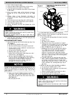
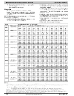
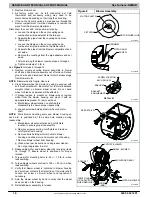
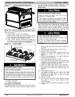
Figure 9

Burner Assembly

B

URNER

 A

SSY

F

LAME

 S

ENSOR

(

B

ELOW

 B

URNER)

F

LAME

 R

OLL

OUT

 S

WITCH

B

URNER

 S

UPT.

 A

SSY

L11F064

Representative drawing only, some models may vary in appearance.

To reinstall burner assembly:

1. Install the Hot Surface Igniter (HSI) and bracket in burner

assembly.

2. Install flame sensor on burner.
3. Align the edges of the one-piece burner with the slots in

the burner assembly and slide the burners forward until

they are fully seated in the burner assembly.

4. Align the orifices in the manifold assembly with the

support rings on the end of the burner.

Содержание N9MSB0401410B

Страница 1: ...and or pictures or product labels The signal word WARNING is used throughout this manual in the following manner Safety alert symbol When you see this symbol on the unit and in instructions or manual...

Страница 2: ...eath WARNING signifies hazards which could result in personal injury or death CAUTION is used to identify unsafe practices which may result in minor personal injury or product and property damage NOTE...

Страница 3: ...am of Furnace Drip Leg Gas Valve turned ON Type of Gas Natural Propane Filter Type and Size Check in box the Blower OFF Delay Jumper Heating Position for Fan Time OFF Setting 1 and 2 2 and 3 3 and 4 5...

Страница 4: ...structure through drain tube Vent gases contain carbon monoxide which is tasteless and odorless WARNING 1 Remove upper and middle collector box drain plugs opposite of the condensate trap See Figure...

Страница 5: ...e at installed altitude from local gas supplier 2 Obtain average yearly gas specific gravity from local gas supplier 3 Find installation altitude range for your installation in the manifold pressure t...

Страница 6: ...manifold pressure is outside this range change main burner orifices h When correct input is obtained replace cap that conceal gas valve regulator adjustment screw Main burner flame should be clear blu...

Страница 7: ...24 VAC CONNECTIONS P2 HOT SURFACE IGNITOR HSI INDUCER MOTOR IND CONNECTOR 115 VAC L1 LINE VOLTAGE CONNECTION SPARE1 COM BLUE 115 VAC L2 NEUTRAL CONNECTIONS 24 V THERMOSTAT TERMINALS HUMIDIFIER TERMINA...

Страница 8: ...300 21 171 343 857 62 58 116 290 22 164 327 818 64 56 112 281 23 157 313 783 66 54 109 273 24 150 300 750 68 53 106 265 25 144 288 720 70 51 103 257 26 138 277 692 72 50 100 250 27 133 267 667 74 48 9...

Страница 9: ...42 3 4 42 3 5 42 3 6 3001 800 43 3 8 42 3 2 42 3 3 42 3 4 915 825 43 3 6 43 3 7 43 3 8 42 3 2 850 44 3 8 43 3 5 43 3 6 43 3 7 875 44 3 6 44 3 7 43 3 4 43 3 5 4000 900 44 3 4 44 3 5 44 3 7 44 3 8 1219...

Страница 10: ...ding Leaving blower door off will result in incorrect temperature measurements due to possible changes in duct static pressure and airflow FURNACE DAMAGE HAZARD Failure to follow this caution may resu...

Страница 11: ...e wires normally connected to thermostat sub base terminals R and W The thermostat anticipator should NOT be in the circuit while measuring current 1 Remove thermostat from sub base or from wall 2 Con...

Страница 12: ...685 1630 1570 1495 1415 1330 1230 Yellow 1445 1430 1410 1385 1350 1305 1255 1195 1120 1045 Orange 1250 1240 1225 1200 1170 1130 1090 1040 975 910 Blue 1090 1080 1060 1035 1010 970 930 885 835 765 Red...

Страница 13: ...and minimum break point of the switch is 0 05 inches of water column from the nominal break point of the switch The maximum make point of the switch is 0 10 inches of water above the maximum break poi...

Страница 14: ...LED 6 A component test sequence will follow 7 Reinstall the Main Control door Component Self Test NOTE The furnace control component test allows all components to run for a short time except the gas v...

Страница 15: ...rvice as necessary 4 Inspect burner compartment before each heating season for rust corrosion soot or excessive dust If necessary have furnace and burner serviced by a qualified service agency 5 Inspe...

Страница 16: ...t on blower wheel remove wheel from the blower housing and wash it with an appropriate degreaser To remove wheel a Mark blower wheel location on shaft before disassembly to ensure proper reassembly b...

Страница 17: ...old or damaging the mounting to the burner assembly ELECTRICAL SHOCK AND FIRE HAZARD Failure to follow this warning could result in personal injury death and or property damage Turn off the gas and el...

Страница 18: ...furnace through two complete heating cycles to check for proper operation 18 Install control door when complete Servicing Hot Surface Igniter The igniter does NOT require annual inspection Check ignit...

Страница 19: ...e tubing to prevent any sags or traps in the tubing 6 Connect condensate drain elbow or drain extension elbow to the condensate trap 7 Connect the leads of the condensate heat pad if used 8 Connect ex...

Страница 20: ...ratures may be 32_ F 0_ C or lower freeze protection measures must be taken to prevent property or product damage CAUTION Since the furnace uses a condensing heat exchanger some water will accumulate...

Страница 21: ...SERVICE AND TECHNICAL SUPPORT MANUAL Gas Furnace N9MSB Specifications subject to change without notice 440 04 4412 01 21 Figure 14 Service Label 338310 2 Rev F...

Страница 22: ...SERVICE AND TECHNICAL SUPPORT MANUAL Gas Furnace N9MSB Specifications subject to change without notice 22 440 04 4412 01 Figure 15 Wiring Diagram 339241 2 Rev A...

Страница 23: ...quence Gas valve and humidifier will not be turned on Inducer motor will start and remain on until the end of the blower test then off The following components are on for 10 15 seconds each individual...

Страница 24: ...onent test Does the igniter glow orange white by the end of the 15 second warm up period Unplug igniter harness from control and repeat component test Check for 115V between connector P2 HSI and NEUTR...

Страница 25: ...ds after the gas valve GV is energized Simultaneously the electronic air cleaner terminal EAC is energized and remains energized as long as the blower motor BLWM is energized f Heat Off Delay When the...

Страница 26: ...dule when used Inducer motor capacitor when used Collector box Condensate trap Condensate trap elbow Gaskets WARNING FIRE EXPLOSION ELECTRICAL SHOCK AND CARBON MONOXIDE POISONING HAZARD Failure to fol...

Страница 27: ...T Two stage FEATURE B Base AFUE Efficiency E Extra AFUE Efficiency C Communicating D Dual Certified 2 pipe or 1 pipe R 2 pipe only S Single stage T Two stage N Standard L Low Nox FEATURE 040 40 000 BT...

Отзывы: