


SERVICE AND TECHNICAL SUPPORT MANUAL
Gas Furnace: N9MSB
Specifications subject to change without notice.
440 04 4412 01
7
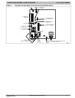
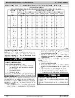
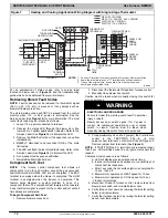
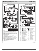
Figure 4
Example of Single Stage Furnace Control for PSC Blower Motor
ÏÏÏ
ÏÏÏ
ÏÏÏ
HEAT
OFF
−
DELAY
COMPONENT TEST
TERMINAL
P1
−
LOW VOLTAGE MAIN
HARNESS CONNECTOR
TRANSFORMER 24
−
VAC
CONNECTIONS
P2
−
HOT SURFACE IGNITOR (HSI) & INDUCER
MOTOR (IND) CONNECTOR
115 VAC
(L1) LINE
VOLTAGE
CONNECTION
SPARE1
COM/BLUE
115
−
VAC (L2) NEUTRAL
CONNECTIONS
24
−
V THERMOSTAT
TERMINALS
HUMIDIFIER TERMINAL
(24
−
VAC 0.5 AMP MAX)
3
−
AMP FUSE
LED OPERATION &
DIAGNOSTIC LIGHT
24VAC/RED
BLOWER SPEED
SELECTION TERMINALS
HUM
XFMR
HUMIDIFIER
TERMINAL
115
−
VAC
120
1
80
90 150
SPARE2
J2 JUMPER
J2
HUM
24VAC
BL
W
SPARE1
SPARE2
L2
NEUTRAL
EAC 1 AMP
IND HSI
P2
L1
SPARE3
SPARE3
P1
1
−
AMP@115VAC
L13F013


