manualshive.com logo in svg
background image

P2 


--------------------------------------------------------------------- 

Installing the Hardware on PC 


Step 1:

 Shut down and power off the computer. 

Step 2:

 Remove all the covers from the computer. 

Step 3:

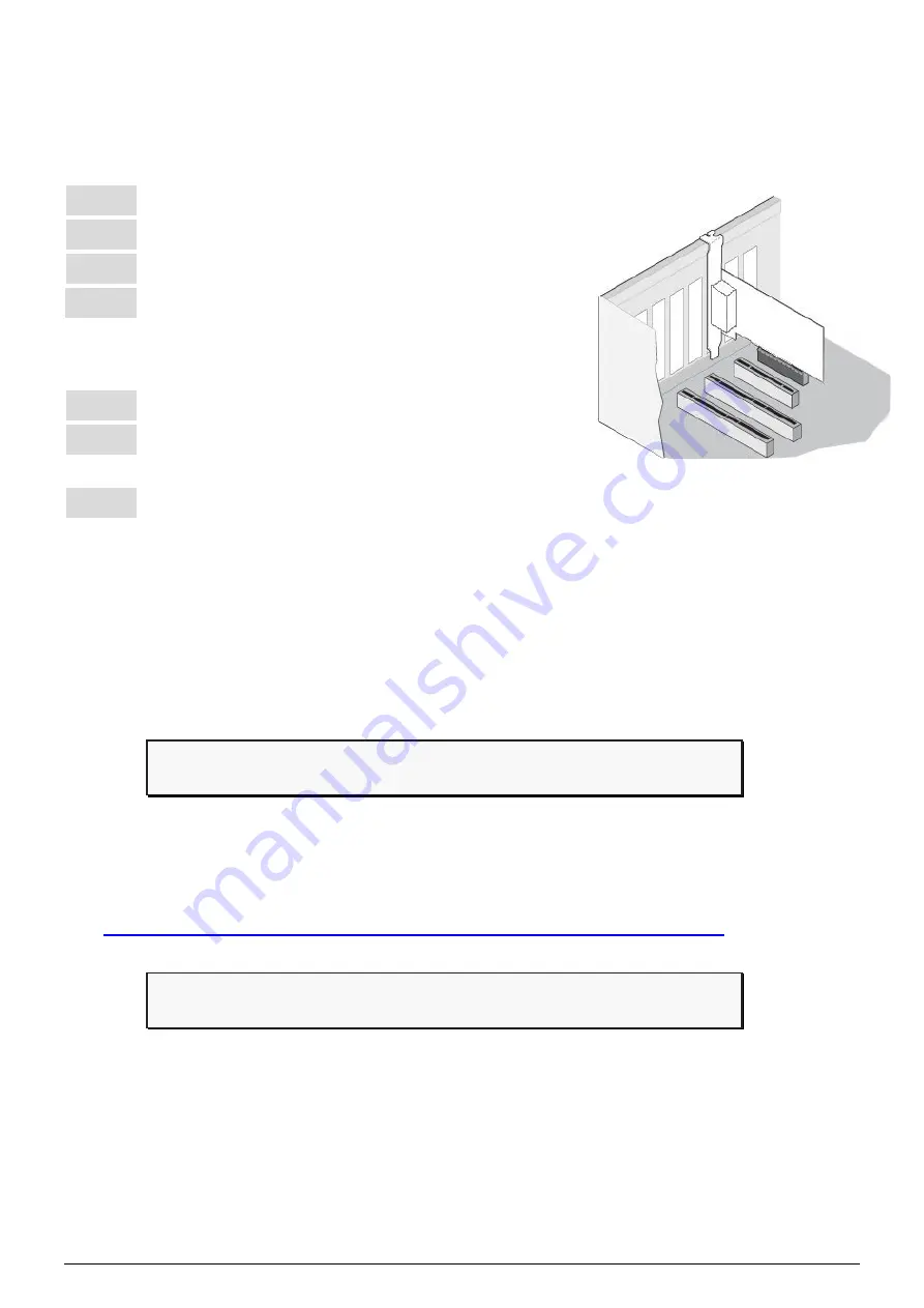
 Select an unused PCI slot. 

Step 4:

 Carefully insert the PISO-CAN200U-FD 

series board into the PCI slot and secure the 
board in place. 

Step 5:

 Replace the covers on the computer. 

Step 6:

 Reconnect the power supply and power on 

the computer. 

Step 7: 

Once the computer reboots, follow section 2 to install the   

windows driver of PISO-CAN200U-FD series board.


--------------------------------------------------------------------- 

Installing Windows Driver 


Step 1: Download or locate the Windows driver. 


The 

KP_CANFD

 driver supports 32/64-bit Windows 7/8.1/10. It is 

recommended that new users install this driver, which can be found in 

the following location. 

https://www.icpdas.com/en/download/show.php?num=3200


Step 2: Start to install Windows driver. 


(1).


Right-click the 

Start

 button or press the 

Windows Logo

 + 

X

 key 

combination on the keyboard and, from the list, click to select 

Device 

Manager


Содержание PISO-CAN200U-FD-T

Страница 1: ...is guide the package includes the following items PISO CAN200U FD T or PISO CAN200U FD D x 1 Technical Support service icpdas com www icpdas com Resources How to search for drivers manuals and spec in...

Страница 2: ...tep 7 Once the computer reboots follow section 2 to install the windows driver of PISO CAN200U FD series board 2 Installing Windows Driver Step 1 Download or locate the Windows driver The KP_CANFD dri...

Страница 3: ...twork Controller device from Other devices item then right click the mouse button Then select Update Driver Software to continue 3 On the Update Driver Software Network Controller screen click the Bro...

Страница 4: ...P4 4 Then Click the Browser button to select the driver directory and click the Next button to start to install the driver 5 Once the installation has been completed click the Close button to exit...

Страница 5: ...in CANFDCard item Pin Assignments for the 5 pin screw terminal connector Pin No Name Description 1 CAN_GND CAN_Gnd signal line for the CAN port 2 CAN_L CAN_Low signal line for the CAN port 3 F G Fram...

Страница 6: ...A Not used 6 CAN_GND CAN_Gnd signal line for the CAN port 7 CAN_H CAN_High signal line for the CAN port 8 N A Not used 9 N A Not used PISO CANFD Utility is provided by ICP DAS to transmit receive CAN...

Страница 7: ...P7 Step 2 Setting up the board Connect the CAN_L and CAN_H pin on port1 and port2 of board Step 3 Active the board Launch the PISO CANFD Utility software...

Страница 8: ...filter prarameters For detail information please refer to section 2 4 Software Utility of user s manual 4 Press the Active buttom to start to use the above setting to send receice CAN messages Step 4...

Отзывы: