PCI-1002 Series Card
12-bit, 110 kS/s or 44 kS/s Multi-function Board
User Manual, Ver. 3.0, Jun. 2018, PMH-015-30, Page: 37
5.1.2
Analog Input Test Wiring
Before beginning the
“Self-Test”
procedure, ensure that the following items are available:
A CA-3710 Cable
(Optional, Website:
http://www.icpdas.com/products/Accessories/cable/cable_selection.htm
)
A DN-37 Terminal Board
(Optional, Website:
http://www.icpdas.com/root/product/solutions/pc_based_io_board/daughter_boards/dn-37.html
)
Provide a stable signal source. (For example, dry battery)
Step 1:
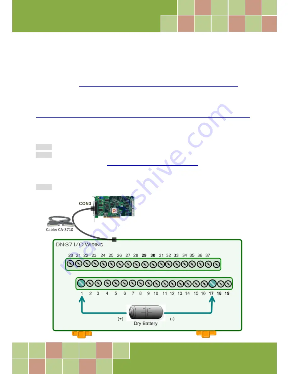
Connect the DN-37 to the CON3 connector on your board using the CA-3710 cable.
Step 2:
Wire the
signal source to AD channel0
, and then keep set the
JP1 jumper to Single-Ended
(default settings,
refer to
Section 2.2 “JP1: AD Input Type Selection”
for more detailed), and
wire the signals as follows:
Step 3:
Connect the
AI 0 (Pin01)
to signal positive (+)
and then
A.GND (Pin17)
to
signal negative (-)
.


