background image

P3 

Before you continue, if you have changed the settings from default then 
it is necessary to open the cover for each I-7530A-MR-FD and 
re-configure their JP3 jumpers to enable them again, as shown in below 
figure. However if the I-7530A-MR-FD

’s still have their default settings 

then it is not necessary to open and reset them because the default 
configuration is enabled.   

Enable (default),   

(Activate)   


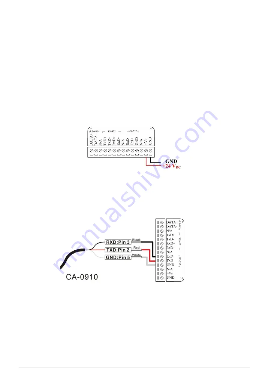
Step2: Power connection for the I-7530A-MR-FD_A and B.   

Connect the +Vs and GND pins of the I-7530A-MR-FD module to 
the DC power supply (10~30V

DC

).     


Step3: RS-232 connection   

Connect the RS-232 ports of the I-7530A-MR-FD_A and 
I-7530AMR-FD_B to the RS-232 COM1 and COM2 of the PC by 
using the attached cable CA-0910 respectively. You can use the 
attached cable CA-0910 to do that.   


Step4: CAN bus connection   

Connect the CAN ports of these two I-7530A-MR-FD modules 
using the following architecture. If necessary, you may refer the 
cable CA-0910-C for wiring conveniently. Please refer to the 
following picture.   

Содержание I-7530A-MR-FD

Страница 1: ...ckage includes the following items 1 I 7530A MR FD RS 232 cable CA 0910 Screw Driver Quick Start Technical Support service icpdas com www icpdas com Resources How to search for drivers manuals and spe...

Страница 2: ...nication interfaces Here we use two I 7530A MR FD modules called the I 7530A MR FD_A and the I 7530A MR FD_B as the example to demonstrate how to use the I7530A MR FD modules The architecture of this...

Страница 3: ...Step2 Power connection for the I 7530A MR FD_A and B Connect the Vs and GND pins of the I 7530A MR FD module to the DC power supply 10 30VDC Step3 RS 232 connection Connect the RS 232 ports of the I...

Страница 4: ...mal switches to the Init position and hold it at least 3 seconds The CAN LED and UART LED of the I 7530A MR FD_A will flash approximately once per second That means that the I7530A MR FD is working in...

Страница 5: ...CAN Utility will show the communication information of the I 7530A MR FD_A module as shown in the following figure Step6 Set the communication mode of the I 7530A MR FD_A Here use Modbus Slave mode fo...

Страница 6: ...ame configurations as the I 7530A MR FD_A 4 Testing the I 7530A MR FDs Step1 Turn off the DC power connected with these two I 7530A MR FD modules Step2 Set the Init Normal switches on the back of the...

Страница 7: ...1 port After the I 7530A MR FD_A receives this command it will convert the Modbus RTU message to the CAN message and send it to the CAN network While the I 7530A MR FD_B receives the CAN message trans...

Страница 8: ...P8 9 8 7 6 Utility B Utility A 5...

Отзывы: