


Technical support:
P5
4
Modbus Address
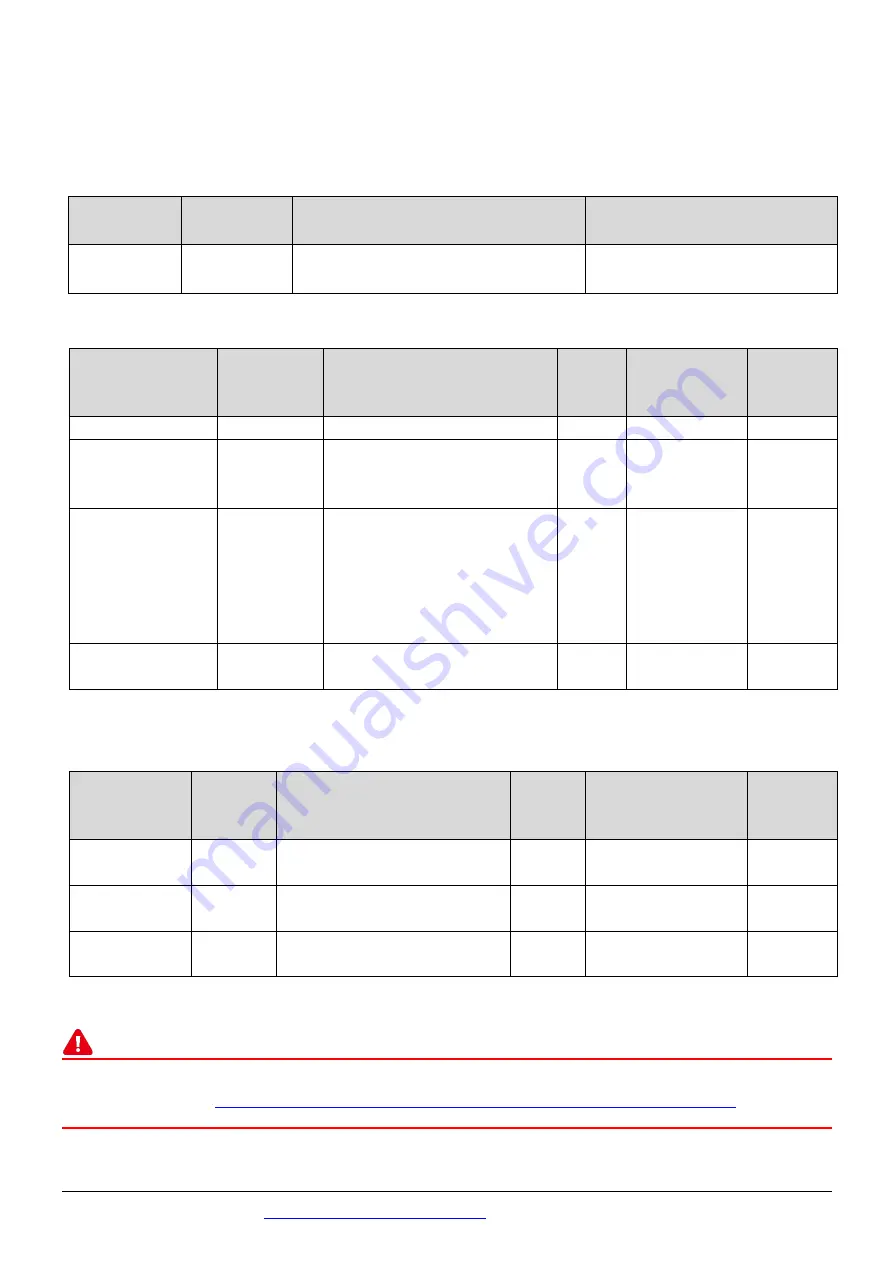
The nDO parameters in the following Modbus Address Tables are as follows:
Mode
Name
Universal
DIO
Number of DO channels
(nDO)
Number of DI channels
(nDI)
ET-2254(P)
16
Depend on your configuration
Depend on your
configuration
(0xxxx) DO address:
Begin
address
Points
Description
Bits
Per
Point
Range
Access
Type
0 (0x0)
1~nDO
Digital Output Channels
1
0: OFF, 1: ON
R/W
.
.
.
.
.
.
.
.
.
.
.
.
.
.
.
.
.
.
299 (0x12B)
1
Force the DI/DO Mode.
0 = Dynamic I/O type based
on DO requests.
1 = Static I/O type by
configuration (web or
Modbus).
1
0 = Dynamic
1= Static
R/W
300 ~315
(0x12C~0x13B)
1 ~ UDIO
Sets the Universal DIO
channels to DI or DO Port
1
0 = DO, 1= DI
R/W
“R”
: Read;
“W”
: Write;
“F”
:
Settings are recorded in flash memory by default
(1xxxx) DI address:
Begin
address
Points
Description
Bits
Per
Point
Range
Access
Type
0
(0x0)
1~nDI
Digital Input
1
0: OFF, 1: ON
R
32
(0x20)
1~nDI
Digital latched status(high)
1
0:no, 1:latched
R
64
(0x40)
1~nDI
Digital latched status(low)
1
0:no, 1:latched
R
“R”
: Read
Note
For detail “DI/DO Modbus Address” information, refer to Section 6.3 Modbus Register Table
of user’s manual (
http://ftp.icpdas.com/pub/cd/6000cd/napdos/et2200/document/
).