manualshive.com logo in svg
background image

INSTRUCTION MANUAL

This device complies with Part 15 of the FCC Rules. Operation is 
subject to the condition that this device does not cause harmful 
interference.

iF80DT/DS

UHF TRANSCEIVER

iF80T/S

The photo shows the IC-F70DT/T 
or IC-F80DT/T.

iF70DT/DS

VHF TRANSCEIVER

iF70T/S

Содержание IC-F70DT

Страница 1: ...es with Part 15 of the FCC Rules Operation is subject to the condition that this device does not cause harmful interference iF80DT DS UHF TRANSCEIVER iF80T S The photo shows the IC F70DT T or IC F80DT...

Страница 2: ...is protected by intellectual property rights including patent rights copy rights and trade secrets of Digital Voice Systems Inc This voice cod ing Technology is licensed solely for use within this Com...

Страница 3: ...as DO NOT modify the transceiver for any reason Optional unit installation should be done at authorized Icom service center only BE CAREFUL The IC F70 F80 series transceivers employ waterproof constru...

Страница 4: ...eys 7 3 BASIC OPERATION 12 18 Turning power ON 12 Channel selection 12 Call procedure 13 Receiving and transmitting 13 User set mode 17 Scrambler function 18 4 BATTERY CHARGING 19 22 Caution 19 Option...

Страница 5: ...Belt clip 1 r Connector cover with screw 1 set q w e r Accessory attachments D Flexible antenna Connect the supplied flexible an tenna to the antenna connector CAUTION NEVER HOLD the antenna when car...

Страница 6: ...leased NEVER release or attach the battery pack when the trans ceiver is wet or soiled This may result water or dust getting into the transceiver battery pack and may result in the transceiver being d...

Страница 7: ...the connector cover q Insert the connector cover into the multi connector w Tighten the screw To detach the connector cover e Unscrew the screw using a phillips screwdriver r Detach the connector cove...

Страница 8: ...ncy call Desired function can be programmed by your dealer p 7 t BUSY TRANSMIT INDICATOR Lights green while receiving a signal or when the squelch is open Lights red while transmitting y MULTI CONNECT...

Страница 9: ...te conditions tog gles audible and inaudible Push the key to mute the channel sets to inaudible only Push the key to unmute the channel sets to audible only Push the key after communication is finishe...

Страница 10: ...activated y BELL INDICATOR Appears blinks when the specific 2 5 tone MDC 1200 code is received according to the pre programming u CALL CODE MEMORY INDICATOR Appears when the call code memory is select...

Страница 11: ...ed use for grouping For example Staff A and Staff B are assigned into a Busi ness zone and John and Cindy are assigned into a Pri vate zone SCAN A START STOP KEY SCNA This key s operation depends on t...

Страница 12: ...KEY LIGT Push to turn the transceiver s backlight ON temporarily only when the backlight function is turned OFF in user set mode LOCK KEY LOCK Push and hold for 1 sec to electronically lock all progra...

Страница 13: ...ON or OFF When this function is turned ON the beep is not emitted and the LCD backlight does not light when a signal is received or a key is pushed etc TX CODE ENTER KEY TXCE PMR operation only Push t...

Страница 14: ...TARY KEYS 01M 02M 03M Push and hold to control the output signal level of the optional ports in the optional unit connector TONE NAC CH SELECT KEY TSEL LMR P25 Conventional operation only While in the...

Страница 15: ...tion functions OFF Encryption transmittion function ON PUSH PUSH PUSH PUSH appears appears appears disappears D For Digital mode operation only INDIVIDUAL KEY INDV Push to enter the individual ID code...

Страница 16: ...cation does not clear after in putting 6 digits the input code number may be incorrect Turn the power off and start over in this case Channel selection Several types of channel selections are availabl...

Страница 17: ...ective calling Non selective calling Receiving and transmitting Receiving q Rotate VOL to turn the power ON w Push CH Up or CH Down or rotate ROTARY SELEC TOR to select a channel in sequence Depending...

Страница 18: ...transmitting Penalty timer Once the time out timer is activated transmission is further inhibited for a period determined by the penalty timer D TX code channel selection If the transceiver has TX Cod...

Страница 19: ...used for setting the digit to the right will blink automatically without pushing TX Code CH Select y Repeat r and t to input all allowable digits u Push Call to transmit IC F70DT T or IC F80DT T only...

Страница 20: ...ransceiver has Talkgroup assigned to it the indication can be toggled between the operating channel number or name and Talkgroup ID code or name When the Talkgroup ID code or name is displayed CH Up o...

Страница 21: ...es to select the appropriate item Then push Up or Down to set the desired level condition Available set mode functions are Backlight LCD Contrast Beep Beep Level Ringer Level SQL Level AF Min Level Mi...

Страница 22: ...e communication between stations The frequency inversion type is equipped to all versions moreover the optional Rolling or Non rolling type can be available q Push Scrambler to turn the scrambler func...

Страница 23: ...ANGER NEVER use or leave battery packs in areas with temperatures above 60 C 140 F High tempera ture buildup in the battery such as could occur near fires or stoves inside a sun heated car or in direc...

Страница 24: ...p it safely in a cool dry place with the temperature range as below 20 C to 45 C 4 F to 113 F within a month 20 C to 35 C 4 F to 95 F within three months 20 C to 25 C 4 F to 77 F within a year D Charg...

Страница 25: ...10 Connectors Screws supplied with the charger adapter Plugs This illustration shows the BC 119N D Rapid charging with the BC 119N AD 110 The optional BC 119N provides rapid charging of battery packs...

Страница 26: ...MULTI CHARGER DC power cable OPC 656 Connect with the DC power supply 13 8 V at least 7 A AC adapter Purchased separately TRANSCEIVER BATTERY PACK Turn power OFF AD 110 charger adapters are installed...

Страница 27: ...of the arrow w first then check the latch is in place e Fig 1 Be sure the gasket is set correctly and do not protrude from the battery case Fig 3 CAUTION When installing batteries make sure they are a...

Страница 28: ...p 2 w Slide the base clip in the direction of the arrow until the base clip is locked and makes a click sound e Clip the belt clip to a part of your belt And insert the trans ceiver into the belt cli...

Страница 29: ...he battery pack if it is attached p 2 e Pinch the clip q and slide the base clip in the direction of the arrow w q w CAUTION HOLD THE TRANSCEIVER TIGHTLY WHEN HANGING OR DETACHING THE TRANSCEIVER FROM...

Страница 30: ...e microphone approx 5 to 10 cm 2 to 4 inches from your mouth and speak in a normal voice level Attachment Attach the connector of the speaker microphone into the SP MIC connector on the transceiver an...

Страница 31: ...ger depending on versions Charging time approx 2 5 hours when BP 253 is attached BC 121N multi charger AD 110 charger adapter 6 pcs BC 157 ac adapter For rapid charging of up to 6 battery packs six AD...

Страница 32: ...ction cannot be guaranteed because of possible damage to these cases or the waterproof seals HS 94 HS 95 HS 97 headset VS 1SC vox ptt case HS 94 Ear hook type HS 95 Neck arm type HS 97 Throat micropho...

Страница 33: ...onstruction Durable construction Equipped with a PTT switch and revolving clip VS 1SC Water protection cover PTT switch MIC VOX gain adjusting pot VOX PTT select switch VOX gain and delay adjustment q...

Страница 34: ...an be set from 0 5 to 3 0 sec 0 5 sec step for a convenient interval before returning to receive 0 5 sec min default X TXC SET 3 0 sec max X TXC SET Up Push Down NOTE MIC VOX gain can be adjusted via...

Страница 35: ...is product Use of accessories other than those specified may result in RF exposure levels ex ceeding the FCC requirements for wireless RF exposure To ensure that your expose to RF electro magnetic ene...

Страница 36: ...re posted to do so DO NOT operate the transmitter in areas that are sensitive to electromagnetic ra diation such as hospitals aircraft and blasting sites Occupational Controlled Use The radio transmit...

Страница 37: ...ructions may cause harmful interference to radio communications However there is no guarantee that inter ference will not occur in a particular installation If this equip ment does cause harmful inter...

Страница 38: ...MEMO...

Страница 39: ...MEMO 1 2 3 4 5 6 7 8 9 10 11 12 13 14 15 16...
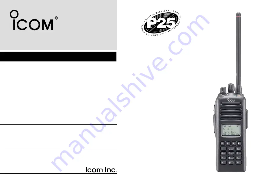
Страница 40: ...1 1 32 Kamiminami Hirano ku Osaka 547 0003 Japan A 6418D 1US t Printed in Japan 2004 2009 Icom Inc Printed on recycled paper with soy ink...

Отзывы: