background image


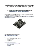
Fan Mod - Cool as ice


Contact author: James Hamelin, KC0RSW


READ ALL OF IT BEFORE PREFORMING THE MOD! 

Use a baby thermometor ( the electric kind w/ the digitial readout ) and see just how hot 

your rig is running before preforming the mod, I know most all of my readings were over 
106F then the thermometer errored out as the temp was too high. 

Tempurature Measurements were made with a baby-tempurature thermometor ( sorry its 
all I had at the time ). 

Heres the Proof! 

---------------- 
top - left front 94.6F 
top - left rear 103.8F 
top - right front N/A (below 85.5F unable to get reading) 
top - right rear 92.7F 
  
Right side front 90.6F 
Right side rear 91.5F 
  
Left side Front 95.0F 
Left side Rear 98.1F 
  

After cw keying for aprox 5 min continous duty the heat generated by the IC-7000 did rise 
enough to enable to the temp control circuit. Heres the good news! 

Once the temp control circuit kicks in, the fan goes into high-rpm mode!!! Then returns to 

'normal' operation with the 2W / 100ohm resistor voltage.  

So with this mod, you get a dual speed fan without any additional modifications!! 

Forgot to mention, when you goto solder the lead to the red wire of the fan, please place a 
rag or something undeneath the area you will be working in ( its pretty tight ) to prevent 

any unwanted solder dripping down onto the main board. 

When closing everything all up, there is a little pink sticky pad ontop of the cover unit to 
access the mars/cap and tvro mod. Place your wire so its right on top of the sticky pad. 
Seemed to be the best place for it at the time. 

Options, the Red wire from the fan connecter to the main board could be snipped between 
the connector and the solder joint to avoid any complications with the temp circuit enabling. 

Additionally, the back left of the rig, still feels warm to the touch but its more of a luke-
warm, instead of what it was previously which was excessivly hot. The back right, front left 
and front right all feel cool to the touch. 

Im sure there are better ways of preforming this modification, although just stealing 0.14A 
from the 12v+ DC on the tuner port seemed to make the most sense, since an LDG Tuner 
only uses 300mA when in operation. 

Although I do not know how this will affect the autotuner as I do not have one, I am unable 

Содержание IC-7000

Страница 1: ...5 on the scale 4 bars First remove the top cover and remove the fan from the radio take a 100ohm resistor and solder a length of wire to each end and cover with heat shrink tubing Cut the red wire to...

Страница 2: ...There are two next to each other and then a couple more We ll call the two stacked the left ones 3 The middle shift register if looking from the front of the radio is the target 4 Locate bank of SMT d...

Страница 3: ...D2154 The solder pads are in the shape of half circles connected by a thin printed trace The thin pc trace can be easily cut with an exacto type knife If present this method eliminates unsoldering th...

Страница 4: ...There are two next to each other and then a couple more We ll call the two stacked the left ones 3 The middle shift register if looking from the front of the radio is the target 4 Locate bank of SMT d...

Страница 5: ...thout any additional modifications Forgot to mention when you goto solder the lead to the red wire of the fan please place a rag or something undeneath the area you will be working in its pretty tight...

Страница 6: ...o vary the speed of the fan 3 Strip the insulation of the red wire to the fan back just enough to make a solder connection to the 100ohm resistor 100ohm pot We used a lighter to burn away a bit of the...

Страница 7: ...w to do Remove the top cover of the radio and unplug the speaker Remove the spring clip of the audio Power Amplifier IC2602 see picture Remove the CPU Logic unit Silver box Remove the DDS unit B6294L...

Страница 8: ......

Страница 9: ......

Страница 10: ...PDF version http www qsl net va3iul Files IC7000_audio_noise pdf Downloaded from mods dk Good luck 73 s Iulian Rosu YO3DAC VA3IUL http www qsl net va3iul...

Страница 11: ...ot have the DSP TX equalizer that I feel should have been implemented The IC 7000 is an excellent radio on transmit but with the HM 151 it s a bit to bassy and it sounds to muffled This can be improve...

Страница 12: ...microphone I know of This is why it will allow a lot of bass to pass through and this is why it will sound bassy compared to other icom hand mics First you must get your hands on the replacement capac...

Страница 13: ...or both Ragchew and DX Only use COMP if necessary Note If your IC 7000 has been modified internally microphone preamp you will probably not notice any difference with this modification This is the cas...

Страница 14: ...plug to the REMOTE jack on the rear panel While pushing and holding P AMP ATT and TUNE CALL turn the transceiver power ON Enter TX adjustment mode Push F 2 TX CAUTION Connect a dummy load to the anten...

Страница 15: ...move the CPU Logic unit Silver box 3 Remove the DDS unit 4 Remove all coaxial plugs and ribbon cables from the board Be extremely careful when removing the two ribbon cables at the front of the radio...

Страница 16: ...Label on IC 7000 box 8 Export model Remove the CPU Logic unit Step 1...

Страница 17: ...Unclip the spring clip situated at the back mid right hand side of the radio Step 2...

Страница 18: ...Remove the DDR unit first then the main board Step 3 Very carefully unplug ribbon cables Don t pull on them Step 4...

Страница 19: ...Original 5 5 MHz SMD ceramic filters Step 5 New 6 MHz Ceramic Trap Filters Step 6...

Страница 20: ...r on the blue screen Press Yes that you acknowledge the warning The radio reverts to the original frequency you had the radio on before embarking on the modification To activate the TV receiver push a...

Страница 21: ...urface device soldering station OM Eddie Leu ZL3TEL for his assistance and photos of the New Zealand expanded frequency range OM Paul Hayden VK4ZBV for information on the Australian and South African...

Страница 22: ...n left and up right and remove the module The diode matrix is visible with D2168 D2169 D2170 en D2172 in place Remove all diodes 3 except D2170 D2168 D2169 D2170 D2171 D2172 1 NO NO NO NO NO 1 6 25 99...

Страница 23: ......

Страница 24: ......

Страница 25: ...existed METHOD 1 Remove the top cover of the radio and unclip the speaker plug 2 Remove the CPU Logic unit Silver box 3 Remove the DDS unit 4 Remove all coaxial plugs and ribbon cables from the board...

Страница 26: ...into the Main board before fitting the Main board to the chassis 11 Replace all screws and tighten 12 Plug in all the cables re fit the CPU Logic unit etc 13 Replace the top cover Don t forget to plug...

Страница 27: ...Remove the CPU Logic unit Step 1...

Страница 28: ...Unclip the spring clip situated at the back mid right hand side of the radio Step 2...

Страница 29: ...Remove the DDR unit first then the main board Step 3...

Страница 30: ...Very carefully unplug ribbon cables Don t pull on them Step 4 Original 5 5 MHz SMD ceramic filters Step 5...

Страница 31: ...New 6 MHz Ceramic Trap Filters Step 6 Original Diode Positions Step 7...

Страница 32: ...front looking towards the back When you switch the power on a warning message will appear on the blue screen Press Yes that you acknowledge the warning The radio reverts to the original frequency you...

Страница 33: ...the bottom of the screen You should now see a picture You can now fine tune the picture by rotating the VFO knob Once everything is tuned perfectly press the volume control set button to store the sta...

Страница 34: ...who have purchased the American model I am working on a modification to change the NTSC system to PAL It involves changing a number of parts on the main board It won t be difficult but procuring the...

Отзывы: