92
BALLGATE:
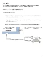
How to measure the voltage at connector P15 when testing your actuators. Do not measure
between the black/blue and orange/blue on P15, you will never see the12VDC.
Use pin 5 or 6 on P11 (where the black wires go to).
Your should see the following:
● When the ball gate is up even in attract if you put the red meter lead in the black/blue on
P15 there should be +12VDC.
● In game play when the ball gate is up, he should see +12V if you move the red meter lead
on the orange/blue at p15.
● If you see +12V when you do both of these things, then the board is working properly.
● It may not be exactly
12V. If it is 11.5 or so, then it is good. If not,
there
some sort of
voltage drop.
WH2134DBX
Main board
Содержание DB1100X
Страница 7: ...7 Assembly for Steps 1 9 Chapter 1...
Страница 14: ...14 STEP 7 Slide two 1S Joists into the two inner channels shown NO HARDWARE is used to secure them...
Страница 16: ...16 Assembly for Steps 9 16 Chapter 2...
Страница 22: ...22 Assembly for Steps 17 22 Chapter 3...
Страница 28: ...28 Assembly for Steps 23 26 Chapter 4...
Страница 33: ...33 Assembly for Steps 28 46 Chapter 5...
Страница 44: ...44 Assembly for Steps 47 54 Chapter 6...
Страница 49: ...49 STEP 52 Tower harnesses Insert cables from each tower assembly into the bottom holes B...
Страница 53: ...53 Assembly for Steps 55 58 Chapter 7 HARDWARE NEEDED AA0655 8 X 3 4 Square pan head QTY6...
Страница 54: ...54 Parts Needed Pallet 2 loose 2F...
Страница 58: ...58 Chapter 8 Assembly for Steps 59 72...
Страница 84: ...84 Tower Covers Part Numbers...
Страница 85: ...85 DECAL PART NUMBERS...
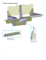
Страница 91: ...91 DB3277X ball gate Assembly NS1022 P802 black NS1022 P509 blue ZS2015X Actuator...

