


ICAR PQS
MAT189 revJ jan18
10
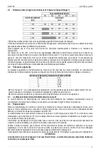
4.1
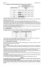
Load break switch terminal distance from the base of the equipment (*)
LOAD BREAK SWITCH (A)
250
400
630
800
1250
CABINET HEIGHT (mm)
DISTANCE
(mm)
1760
455
405
395
380
367
1960
353
342
325
320
2160
303
290
280
268
2360
265
255
240
(*) Distances apply only to the MULTImatic cabinets in the catalogue.
Connect the earthing system (ground) via suitably sized cable, as prescribed by regulations, to the earth terminals
located inside the various units.
We stress that the earth conductor must never be electrically interrupted neither inside nor outside the unit.
Connect terminals S1 and S2 (S11 and S12 for the MIDImatic and MULTImatic equipment) to the secondary of a
current transformer with secondary current 5A inserted on phase L1 (R) (see Attachment B). In order to ensure correct
operation of the automatic control it is essential for the unit to be connected as described in the above attached
document which also illustrates some typical connection errors.
The current transformer, besides being of high quality, is a measuring instrument and not merely a display instrument,
therefore it should possess certain characteristics, namely:
4.2
Apparent power
The Apparent Power of the current transformer (expressed in VA) should be such as to meet the levels of self-
consumption at both the current input of the controller used and the connecting cable (see table below).
Cable size [mm
2
]
VA per meter of cable at 20°C
2,5
0,41
4
0,254
6
0,169
10
0,0975
16
0,062
For each 10°C variation in temperature, the VA absorbed by the cables are increased by 4%; the values given
above are deduced from typical resistances of flexible cables, class 5
Minimum size of connection of cables between current transformer and controller.
4.3
Current transformer amperage
The primary amperage of the current transformer should be determined by the user solely in relation to the current
drawn by the load whose phase is to be corrected.
4.4
Location
Position the current transformer upstream of the entire load, capacitor bank included, on phase L1 (R) referred to the
power factor correct unit, but downstream of any fixed capacitors dedicated to power factor correction of the transformer
MV/LV.
Install the current transformer on the mains with the side marked by the letter “P1” facing the power supply source and
the side marked by the letter “S1” facing the load (side where there is also the power factor correction system).
The system is now in condition for putting into service. However, first of all it is absolutely necessary to check that it is
suitable for the conditions of the mains to which it has been connected.
Check, with appropriate measurements, that the mains voltage is congruent with the nominal characteristics given on
the nameplate.
After connection and before powering up the system, it is recommended to make sure that no foreign matter produced
by the machining operations, have been lodged inside the unit.
It is also important to remember to refit the guards on the switch or disconnect switch provided on the unit.
CAUTION!
Before putting the power factor correction cabinet into service, it is essential to close all openings machined
for cable entry by means of suitably shaped plates.
Total removal of the cable entry plates, whether on the top or bottom of the cabinet, could cause damage to
the unit by ingress of foreign matter inside it, besides impairing correct operation of the forced ventilation
system.
Содержание MICROmatic
Страница 8: ...ICAR PQS MAT189 revJ jan18 8 ...
Страница 14: ...ICAR PQS MAT189 revJ jan18 14 ...
Страница 21: ...ICAR PQS MAT189 revJ jan18 21 ...


