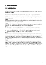
IC Realtime ICIP D2010IR Скачать руководство пользователя страница 12


3


Device Installation  

3.1


Installation Steps  

Important 

Before the installation, please make sure the installation environments can at least support 3x 

weight of the camera.


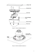
Please follow the steps listed below to install the device.  Please refer to Figure 3-1 for reference. 

Step 1 

Use inner hex wrench in the accessories bag to open dome enclosure by unfastening three inner hex 

screws on enclosure.  

Step 2 

Please take the installation position map in the accessories bag, and then paste it on the ceiling or the 

wall according to your monitor area requirements.  

Step 3 

Find cross signs on the map, and dig three plastic expansion bolts holes in the installation surface and 

then insert three expansion bolts in the holes. Secure these three bolts firmly.  

Note: 


If use pulls out cable from top of installation surface, you must dig a exit hole on installation 

surface according to the installation position map.  


If user pulls out cable from side of cable channel, it must go through the U-shape channel on 

dome pedestal, and take out cable from the side exit hole on pedestal.  

Step 4 

Adjust the device installation pedestal to the proper position and then pull cable through the exit hole 

on Installation surface. Make direction of TOP sign same as it on installation position map. Line up the 

three screw holes in the device pedestal to the three plastic expansion bolt holes in the installation 

position. Put the three self-tapping screws in the three plastic expansion bolts firmly. Fix dome body on 

installation surface.  
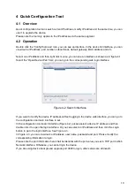
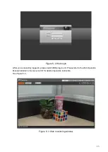
Step 5 

Hold bottom of bracket with hand, horizontally rotate bracket, adjusting lens direction to designated 

position. Loosen one M2 screw on LED decoration cover (loosen only, do not take it down), hold the 

decoration cover with hand, making lens rotate vertically. Adjust vertical direction of lens to appropriate 

angle, and fasten the M2 screw. Range of lens: vertical (0

°~

+65

°

), horizontal (0

°~

+355

°

). See 

Figure 3-2.  

Содержание ICIP D2010IR

Страница 1: ...HD IR Vandal Proof Network Dome Camera User s Manual Version 1 2 2...

Страница 2: ...r Network camera This user s manual is designed to be a reference tool for your system Please read the following safeguard and warnings carefully before you use this series product Please keep this us...

Страница 3: ...n Please install the proper power cut off device during the installation connection Always follow the instruction guide the manufacturer recommended 4 Qualified engineers needed All the examination an...

Страница 4: ...al component do not touch the enclosure when you are installing the device or clean the enclosure when you are doing maintenance work Please use professional optical clean method to clean the enclosur...

Страница 5: ...ture 4 2 1 Components 4 2 2 Framework and Dimension 4 3 Device Installation 7 3 1 Installation Steps 7 4 Quick Configuration Tool 10 4 1 Overview 10 4 2 Operation 10 5 Web Operation 12 5 1 Network Con...

Страница 6: ...rver backup function in accordance with your configuration and setup in alarm or schedule setting Support record via Web and the recorded file are storage in the client end PC Support network storage...

Страница 7: ...r and is valid only when exposure mode is auto with range 1 100 Exposure Mode Manual Low noise Low motion blur Auto It ranges from 1 3 to 1 100000 Video Compression Standard H 264 H 264H MJPEG Video F...

Страница 8: ...Port 10 100 Base T Ethernet Network Protocol Standard HTTP TCP IP ARP IGMP ICMP RTSP RTP UDP RTCP SMTP FTP DHCP DNS DDNS PPPOE UPNP NTP Bonjour SNMP QoS 802 1x Platform Standard PSIA ONVIF Remote Oper...

Страница 9: ...ormation 2 2 Framework and Dimension Please refer to the following two figures for dimension information The unit is mm See Figure 2 2 to Figure 2 4 Component Component Name Component 1 Dome body Comp...

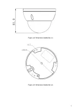
Страница 10: ...5 Figure 2 2 Dimension illustration 1 Figure 2 3 Dimension illustration 2...

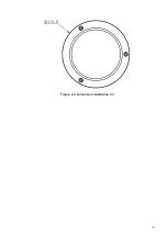
Страница 11: ...6 Figure 2 4 Dimension illustration 3...

Страница 12: ...urface according to the installation position map If user pulls out cable from side of cable channel it must go through the U shape channel on dome pedestal and take out cable from the side exit hole...

Страница 13: ...8 Figure 3 1 Device installation illustration 1 Figure 3 2 Device installation illustration 2...

Страница 14: ...e Reset button in Figure 3 2 for 1 to 2 seconds while connecting device to power then press WPS button on the router Generally the device can be connected to corresponding router within 1 minute suppo...

Страница 15: ...n interface Figure 4 2 Search interface If you want to modify the device IP address without logging in the device web interface you can go to the configuration tool main interface to set In the config...

Страница 16: ...uration tool main interface is shown as below See Figure 4 4 Figure 4 4 Main interface For detailed information and operation instruction of the quick configuration tool please refer to the Quick Conf...

Страница 17: ...the PC and the network camera respectively Network camera default IP address is 192 168 1 108 Subnet mask is 255 255 255 0 Gateway is 192 168 1 1 Use order ping network camera address to check connect...

Страница 18: ...gin After you successfully logged in please install WEB plug in unit Please refer to the Web Operation Manual included in the resource CD for detailed operation instruction See Figure 5 3 Figure 5 3 W...

Страница 19: ...r Network connection error occurred Invalid network setup Invalid user name or password I can not play the download file There is no player There is no DX8 1 or higher For the MEDIA PLAYER there shall...

Страница 20: ...toxic or hazardous substance or elements contained in products will not leak or mutate so that the use of these substances or elements will not result in any severe environmental pollution any bodily...

Отзывы: