background image

ic audio GmbH
Boehringerstraße 14a; D-68307 Mannheim; Germany
Fon: + 49(0) 621 / 77096-0; Fax: + 49(0) 621 / 77096-26
E-Mail: [email protected];  www.ic-audio.com

DT

6

3.MIC 5 /LINE 1~MIC 6/LINE 2 Pegelsteller 
Für die Pegel-Einstellung von MIC 5 ~ 6 oder der Signalstärke LINE 1 ~ 2.

4.Klangseinsteller für MIC 5 ~ 6 oder LINE 1 ~ 2
Für die Feinabstimmung der Höhen und Tiefen der Mikrofone / der LINE-Eingänge.
MIC 5 ~ 6 und  LINE 1 ~ 2.

5.REMOTE, SOURCE AUX 1 ~ 3 Pegelsteller, um den Pegel von SOURCE, AUX 1 ~ 3 einzustellen. 
Wenn Remote ausgewählt ist, ist die Fernsteuereinheit MT-WCP-6 in der Lage, das Gerät zu steuern. 
Wenn „Source“ oder AUX 1 bis 3 ausgewählt ist, können Benutzer einfach mittels Potentiometer die
Lautstärke regeln.

6. Klangseinsteller für SOURCE und AUX 1 ~ 3.
Für die Feinabstimmung der Höhen und Tiefen von SOURCE und AUX 1 ~ 3. 

7.REMOTE, SOURCE, AUX 1 ~ 3 Auswahlschalter und Anzeigen
Taste um zwischen REMOTE, SOURCE oder AUX Eingang zu wählen. Die LED leuchtet, wenn   
REMOTE, SOURCE oder AUX Eingang ausgewählt ist. REMOTE, SOURCE-und AUX-Eingänge können 
nacheinander gewählt werden.  „REMOTE“ ist nur verfügbar wenn die Fernsteuerheit MT-WCP-6 
angeschlossen ist.

8. MASTER Pegelsteller.
Einstellung des Gesamt-Ausgangspegels des Gerätes.

9. Power LED
Wenn das Gerät eingeschaltet ist, leuchtet die LED in blauer Farbe. 
Wenn das Gerät ausgeschaltet ist, leuchtet die LED nicht.

10.Fault LED
Die LED leuchtet, wenn die Pilotton-Überwachung einen Fehler bei einem internen oder externen 
Verstärker feststellt.

11. “All ZONE”-Taste
Wenn Sie diese Taste drücken, werden alle Ausgangszonen aktiviert, jedes LED der Zonen leuchtet auf.

12.LED VU-Anzeige.
Anzeige des output signal Levels.

13.ZONE 1 ~ 6 Auswahltasten und Anzeige
Drücken Sie die Zonentaste(n) um eine Zone(n) auszuwählen. Jede Zone kann eigenständig ausgewählt 
werden. Ausgewählte Zonen werden per leuchtender LED signalisiert. Wenn einer der Sprechstellen, 
TEL oder MIC 1-Eingang in Betrieb ist, leuchtet die grüne LED-Anzeige. 

14. Zonen-Pegelsteller
Zum Einstellen des Pegels für die jeweilige Beschallungszone.

15. Optionaler Modul-Eingang
Dieser Eingang kann für den Einbau des 

MT-CDT-USB Moduls genutzt werden (optionale Musikquelle 

mit CD/MP3-Player, SD-Card-Reader, USB-Eingang und Tuner)


MT-AMP 1000

ic audio

Содержание MT-AMP 1000

Страница 1: ...ic audio Status 09 2014 User manual to make people listen MT AMP 1000 Six Zone Mixer Amplifier ...

Страница 2: ...9 0 621 77096 0 Fax 49 0 621 77096 26 E Mail info ic audio com www ic audio com EN 2 1 Images IMPORTANT Before installing or operating this product please always read this manual carefully WARNING To prevent the risk of fire or electric shock never expose this product to rain or humidity ...

Страница 3: ...ch Setting 12 10 Microphone Installation 15 11 Music Source Input 17 12 Connection of TEL EMG I P 18 13 MOH 18 14 Connection of callstations 19 15 Wall control panel 19 16 Ext Amp Ext Amp In 20 17 REC out Power in PRE out 20 18 Connection of output zones 21 19 0 8Ω 70V 100V input 21 20 Power Remote Control 22 21 Battery Back up connection 22 22 Maximum connection cable lengths 23 23 Block diagram ...

Страница 4: ...y it also has independent volume control and HI LO control VR Z1 Z6 has independent key and LED indicator Each zone has attenuator switch to control output level The unit has All Zone control key it can manage all Zone s output The VU meter indicates the output signal level MIC1 has RJ45 terminal for the connection of the callstation MT PM 01 Telephone emergency has the top priority and operating ...

Страница 5: ...ail info ic audio com www ic audio com EN 5 6 Front Panel MT AMP 1000 5 System Installation Diagram ic audio 1 MIC 1 4 Level Control To adjust MIC 1 4 microphone level 2 HI LO Frequency Control for MIC 1 4 Adjust high and low frequency response of MIC 1 4 Set at center click provides flat frequency response ...

Страница 6: ...AUX input is selected REMOTE SOURCE and AUX inputs can be selected sequentially REMOTE is available only when the wall panel is activated 8 MASTER Volume Control Adjust overall output signal level of the unit 9 Power LED When it is power on the power LED will light up in blue color When it is power off the power LED will be off 10 Fault LED LED will light up when the pilot tone detecting circuit f...

Страница 7: ...ent and voltage rating 20 Chassis Ground A Chassis Ground should be connected during installation 21 DC 24V Input Terminal Input terminal to connect DC 24V power source Note Never connect to the wrong polarity of DC power source 22 Direct Output Terminals Direct Speaker output terminal voltage are 0 8Ω 70V 100V This is unable to be switched when other ZONE outputs are selected 23 Power Remote ON O...

Страница 8: ...uncing MIC has the first priority 10 the new announcing MIC can override other MIC 11 All the MICs have the same priority 27 Chime MODE DIP Switch There are 2 pins of DIP switch to select the chime mode Set the DIP switch as follows 00 Chime off 01 Chime 1 1 tone 10 Chime 2 2 tones 11 Chime 3 4 tones 28 CHIME VR Adjust chime output level Note Short the trigger contact pins of RJ45 42 will create c...

Страница 9: ... for MIC 3 4 37 MIC3 XLR INPUT MIC3 is balanced microphone input MIC3 1 5mV 600Ω balanced 38 MIC2 XLR INPUT MIC2 is balanced microphone input MIC2 1 5mV 600Ω balanced 39 MIC 1 2 Phantom Power ON OFF To switch ON OFF the phantom power of MIC 1 2 40 PTT DIP Switch Set the PTT dip switch at ON Mic 1 will be muted MT PM 01 can give speech to all zones with chime signal Set the PTT dip switch at OFF MT...

Страница 10: ...allstations 50 Wall Control Panel Terminal RJ 45 terminal can be connected to Wall Control Panel MT WCP 6 When wall control panel is activated the remote LED will light up Then Wall Control Panel can control the ZONE output of main unit select SOURCE AUX1 3 and adjust the Master output level 51 XLR out for Ext Amplifier 0 dB 600次 balanced XLR output terminal It is the output of whole preamplifier ...

Страница 11: ...ZONE 1 6 Output Terminal ZONE 1 6 each ZONE can be selected independently Each ZONE has 100V 0 terminals 59 AM FM Input Terminal To connect external AM FM antenna 8 Installation 8 1 Open the packing box 1 Take out the unit 2 Check the accessories 8 2 Read the manual before install the system 8 3 Optional Install unit in rack The MT AMP 1000 is designed for table top use If user wants to use in the...

Страница 12: ...ower amplifier In mode 2 the call signal will go through the call power amplifier to announce on those selected Zones and the other Zones which are not selected during call announcement will remain to play BGM signal 9 2 Set 20KHZ switch Set the switch downward there will 20KHZ pilot tone signal created The 20KHZ detecting function will be activated The external amplifier acts at standby amplifier...

Страница 13: ...m www ic audio com EN 13 MT AMP 1000 9 3 Set priority of Mic 1 6 Set the priority switch of following 0 0 MIC1 2 3 4 5 6 1 0 The new announcing MIC can override other MIC 1 1 All the MIC have the same priority 0 1 The announcing MIC has the first priority Above are the four different priority modes of microphone input ic audio ...

Страница 14: ... 49 0 621 77096 26 E Mail info ic audio com www ic audio com EN 14 MT AMP 1000 9 4 Set Chime mode There are 4 different chime modes 0 0 Chime off 0 1 Chime 1 1 0 Chime2 1 1 Chime3 Note The callstation generate chime signal itself it will not trigger chime signal of MT AMP 1000 ic audio ...

Страница 15: ...t have the priority to other microphone inputs 10 1 2 XLR input and PTT setting a Set the PTT at ON b Insert the XLR input The Mic 1 will override and mute all the other inputs except TEL Emer 100V input 10 1 3 All call paging station a Insert MT PM 01 to the RJ45 32 b Set the PTT at ON c Press to give announcement There will be chime first when the PTT key of MT PM 01 is pressed d Release the PTT...

Страница 16: ...IC 2 a Connect the microphone to MIC2 input b Select the phantom power c For condenser microphone set the phantom power switch to ON For dynamic microphone set the phantom power switch OFF 10 3 MIC3 MIC4 a Connect the microphone to MIC3 and MIC4 input b Select phantom power switch to ON downward for condenser microphone and to OFF upward for dynamic microphone ic audio ...

Страница 17: ...sensitivity will be 200mV it is available for music source signal input c Set at phantom position will supply phantom power for condenser microphone input d Set at MIC5 MIC6 there will not be phantom power output it is available for dynamic microphone There are two kinds of input terminal for music source Both are unbalanced type signal input AUX1 2 3 can be connected to different music source suc...

Страница 18: ...00 source module AUX1 AUX2 AUX3 can be sequentially selected The relative LED will light up 12 1 TEL EMG I P GND The input of GND is a balanced input signal from telephone 12 2 TEL EMG I P 0 100V The 0 100 pick up signal from output signal of amplifier it is used for long distance broadcasting Adjust TEL level to control the input signal level of TEL EMEG Two type of MOH O P one is balanced O P si...

Страница 19: ...inal 50 Press the activate push switch of MT WCP 6 and push the select switch of MT AMP 1000 to select remote LED ON b The wall panel can control the MT AMP 1000 c The MT WC 6 is able to control the Z1 to Z6 output d It is also can select music source and AUX1 AUX2 AUX3 by select key e The user can give speech through microphone XLR input f It can insert external LINE in signal to mix with microph...

Страница 20: ...e dip switch setting 17 REC out Power in PRE out The REC Out RCA connector can be connect to tape recorder or other recording equipment to record signal Use shorting bar to short between power in and PRE out or use RCA cable to connect with external audio processor MT AMP 1000 ic audio GmbH Boehringerstraße 14a D 68307 Mannheim Germany Fon 49 0 621 77096 0 Fax 49 0 621 77096 26 E Mail info ic audi...

Страница 21: ...dance MT AMP 1000 ic audio GmbH Boehringerstraße 14a D 68307 Mannheim Germany Fon 49 0 621 77096 0 Fax 49 0 621 77096 26 E Mail info ic audio com www ic audio com EN 21 19 0 8 Ω70V 100V output The 0 8 70V 100 is a fix output terminal it will not be controlled when other Zone switches are operating Ω Note The total equivalent load impedance should not be lower than the rated load impedance ic audio...

Страница 22: ...wer remote control terminal can switch on the MT AMP 1000 by external control switch To implement this function the power switch of MT AMP 1000 should be at OFF position 21 Backup battery connection backup battery Two 12V batteries are connected to the DC24V terminal It will back up the power source when AC power is power off Note Never connect to the wrong polarity of batteries ic audio ...

Страница 23: ...line However if they will be distributed over the cable run more length is allowed but in total not more than 500 Meters 1 callstation MT PM 06 without keyboard extension 500 Meters 1 callstation MT PM 06 with 4 keyboard extensions MT PM K12 500 Meters 6 callstations MT PM 06 without keyboard extension 400 Meters 6 callstation MT PM 06 with 4 keyboard extensions MT PM K12 100 Meters If cable run w...

Страница 24: ...ic audio GmbH Boehringerstraße 14a D 68307 Mannheim Germany Fon 49 0 621 77096 0 Fax 49 0 621 77096 26 E Mail info ic audio com www ic audio com EN 24 MT AMP 1000 ic audio 23 ...

Страница 25: ...ic audio GmbH Boehringerstraße 14a D 68307 Mannheim Germany Fon 49 0 621 77096 0 Fax 49 0 621 77096 26 E Mail info ic audio com www ic audio com EN 25 MT AMP 1000 ic audio 24 ...

Страница 26: ...A terminal Power In 1V 600Ω unbalanced RCA terminal Paging Station 1V RJ45 terminal TEL EMEG 100mV 600Ω balanced Input Wall Control Panel 1V RJ45 terminal 100V Input 100V balanced Input Ext Amp in 100V input REC Out 1V unbalanced RCA Jack PRE Out 1V unbalanced RCA Jack Ext Amplifier XLR out 1V balanced XLR Jack MOH 0 8Ω 8Ω 1W unbalanced MOH 600Ω 600Ω output 1Vrms balanced Direct Output 100V 70V 8Ω...

Страница 27: ...itch to select ON OFF MIC Pri 2 DIP switches to select 4 different priority modes DIP Switch Setting Chime 2 DIP switches to set 4 different chime modes MIC 1 6 Rotary Source AUX 1 3 Rotary Vol Control Master Rotary VOX Mute Level Rotary TEL Level Rotary MOH Level Rotary Level Control Chime Level Rotary Zone Output Att Zone 1 6 Rotary 6 steps ZONE 1 6 6 tact switches ALL 1 tact switch Remote Sourc...

Страница 28: ...ic audio to make people listen ic audio GmbH Boehringerstraße 14a D 68307 Mannheim Germany Fon 49 0 621 77096 0 Fax 49 0 621 77096 26 www ic audio com E Mail info ic audio com ...

Страница 29: ...ic audio Status 09 2014 Bedienungsanleitung to make people listen MT AMP 1000 6 Zonen Mischverstärker ...

Страница 30: ... 49 0 621 77096 26 E Mail info ic audio com www ic audio com 1 Produktbilder WICHTIG Vor der Installation und Bedienung dieses Produkts bitte immer die Gebrauchsanleitung sorgfältig lesen Um das Risiko eines Brandes oder eines Kurzschlusses zu minimieren das Gerät bitte immer vor Feuchtigkeit schützen DT 2 ...

Страница 31: ...lation 11 9 DIP Schalter Einstellung 12 10 Mikrofon Installation 15 11 Musik Quellen Eingang 17 12 Anschluss TEL EMG 18 13 MOH Ausgang 18 14 Anschluss der Sprechstellen 19 15 Fernsteuereinheit 19 16 Ext Amp Ext Amp Eingang 20 17 REC out Power in PRE Ausgang 20 18 Anschluss der Lautsprecher Ausgangs Zonen 21 19 0 8Ω 70V 100V Ausgang 21 20 Fernstart 22 21 Batterie Anschluss 22 22 Maximale Anschlussk...

Страница 32: ...ine 1 MIC6 Line 4 kann entweder als Mikrofon oder LINE Eingang genutzt werden SOURCE und AUX1 2 3 Auswahl Schalter mit Klangeinstellung Z1 Z6 mit jeweils eigenständigem Auswahlknopf und LED Anzeige Der Ausgangspegels jeder Zone kann separat geregelt werden Das Gerät verfügt über eine Taste zur gleichzeitigen Regelung aller Zonen MASTER Ein VU Meter zeigt den Ausgangspegel MIC1 hat einen RJ45 Einga...

Страница 33: ...0 621 77096 26 E Mail info ic audio com www ic audio com DT 5 6 Vorderansicht Gerät MT AMP 1000 5 Übersicht System Installation ic audio 1 MIC 1 4 Pegel Steller für die Einstellung der Pegel MIC 1 4l 2 Klangsteinsteller für MIC 1 4 Für die Feinabstimmung der Höhen und Tiefen der Mikrofone ...

Страница 34: ...UX Eingänge können nacheinander gewählt werden REMOTE ist nur verfügbar wenn die Fernsteuerheit MT WCP 6 angeschlossen ist 8 MASTER Pegelsteller Einstellung des Gesamt Ausgangspegels des Gerätes 9 Power LED Wenn das Gerät eingeschaltet ist leuchtet die LED in blauer Farbe Wenn das Gerät ausgeschaltet ist leuchtet die LED nicht 10 Fault LED Die LED leuchtet wenn die Pilotton Überwachung einen Fehle...

Страница 35: ...herung gegen Überstrom einzusetzen Wichtig Bitte immer eine Sicherung mit der korrekten Spannung verwenden 20 Gehäuse Erdung Das Gerät sollte bei der Installation geerdet werden 21 DC 24V Input Terminal Eingang für DC 24V Batteriespannung Wichtig Bitte die richtige Polung beachten 22 Direkte Lautsprecher Ausgänge Direkte Lautsprecher Ausgänge mit 0 8 Ohm 70V 100V Dies können nicht verwendet werden...

Страница 36: ...Betrieb genommene Mikrofon hat Priorität 10 Das nachfolgend in Betrieb genommene Mikrofon hat Priorität und damit Vorrang vor dem zuvor in Betrieb genommenen 11 Alle Mikrofone haben die gleiche Priorität 27 Chime Gong MODE DIP Schalter Wählen Sie die Position der beiden DIP Schalter für die gewünschte Gong Funktion 00 Gong Aus 01 Gong 1 1 Klang Gong 10 Gong 2 2 Klang Gong 11 Gong 3 4 Klang Gong 28...

Страница 37: ...rischer Mikrofon Eingang MIC3 1 5mV 600 kOhm symmetrisch 38 MIC2 XLR INPUT MIC2 ist ein symmetrischer Mikrofon Eingang MIC2 1 5mV 600 kOhm symmetrisch 39 MIC 1 2 Power ON OFF Schalter Phantomspeisung Ein Ausschalter für MIC 1 2 40 PTT Push to talk DIP Schalter Stellen Sie den PTT DIP Schalter auf ON MIC 1 wird stummgeschaltet Die Sprechstelle MT PM 01 kann nun Durchsagen in alle Zonen mit Vorgang ...

Страница 38: ...J45 Buchse für den Anschluss von Sprechstellen Bis zu 6 Sprechstellen können angeschlossen werden 50 Wall Control Panel Terminal RJ45 Buchse für den Anschluss der Fernsteuereinheit MT WCP 6 Das remote LED leuchtet auf sobald die Fernsteuereinheit aktiviert ist Die Fernsteuereinheit kann dann die Zonenwahl die Einstellung der Lautstärke und die Quellenwahl durchführen 51 XLR out für Ext Verstärker ...

Страница 39: ...00V Anschlüsse 59 AM FM Input Terminal Für den Anschluss einer AM FM Antenne 8 Installation 8 1 Öffnen Sie die Verpackung 1 Nehmen Sie aus Gerät vorsichtig aus der Verpackung 2 Prüfen Sie den Packungsinhalt 8 2 Lesen Sie die Bedienungsanleitung vor der Inbetriebnahme des Gerätes 8 3 Optional Installation in einem 19 Rack Der MT AMP 1000 ist als Tischgerät konzipiert Falls Sie das Gerät in ein 19 R...

Страница 40: ...ternen Verstärker als Rufverstärker anschließen und verwenden Im Modus 2 haben Sie den Vorteil dass Sie Durchsagen in selektierte Zonen machen können ohne die Hintergrundmusik in den anderen Zonen dabei abzuschalten 9 2 20KHZ Schalter Legen Sie den Schalter nach unten um einen 20KHz Pilotton zu generieren Damit wird die 20KHz Überwachungsfunktion aktiviert Der externe Verstärker agiert dabei als R...

Страница 41: ...00 9 3 Prioritäteneinstellung der Mikrofone 1 6 Sie haben folgende Einstellungsmöglichkeiten per DIP Schalter 0 0 MIC1 2 3 4 5 6 1 0 Das nachfolgend in Betrieb genommene Mikrofon hat Priorität und damit Vorrang vor dem zuvor in Betrieb genommenen 1 1 Alle Mikrofone haben die gleiche Priorität 0 1 Das zuerst in Betrieb genommene Mikrofon hat Priorität ic audio ...

Страница 42: ... 621 77096 0 Fax 49 0 621 77096 26 E Mail info ic audio com www ic audio com DT 14 MT AMP 1000 9 4 Moduswahl Gong Sie können 4 verschiedene Gong Modi per DIP Schalter auswählen 0 0 Gong Aus 0 1 Gong 1 1 Klang Gong 1 0 Gong 2 2 Klang Gong 1 1 Gong 3 4 Klang Gong ic audio ...

Страница 43: ...g a Stellen Sie PTT push to talk auf ON b Schließen Sie Ihr Mikrofon an den XLR Eingang an Das Mic 1 wird Priorität gegenüber den anderen Mikrofonen und weiteren Eingängen haben außer gegenüber dem TEL Emer 100V Eingang 10 1 3 Sammelrufsprechstelle MT PM 01 a Verbinden Sie die MT PM 01 mit dem RJ45 Eingang 32 b Stellen Sie PTT auf ON c Drücken Sie dauerhaft den PTT Schalter der Sprechstelle für ei...

Страница 44: ...2 MIC 2 a Verbinden Sie Ihr Mikrofon mit dem MIC2 XLR Eingang b Wählen Sie nach Bedarf Phantomspeisung wird bei dynamischen Mikrofonen nicht benötigt für das Mikrofon per DIP Schalter nach unten 10 3 MIC3 MIC4 a Verbinden Sie Ihre Mikrofone mit dem MIC3 MIC4 XLR Eingängen b Wählen Sie nach Bedarf Phantomspeisung für die Mikrofone per DIP Schalter nach unten ic audio ...

Страница 45: ...chkeit bei 200mV und damit für das Signal von Musikquellen geeignet c Per Schiebeschalter können Sie auch die Phantomspeisung für die beiden Mikrofoneingänge aktivieren d Set at MIC5 MIC6 there will not be phantom power output it is available for dynamic microphone Es gibt zwei verschiedene Arten von Eingängen für den Quelle Anschluss XLR AUX1 und Cinch AUX 2 AUX3 Alle Eingänge sind unsymmetrisch ...

Страница 46: ...und AUX1 AUX2 AUX3 Die aktive Quelle wird durch eine leuchtende LED angezeigt 12 1 TEL EMG I P GND Der Eingang GND ist ein symmetrischer Eingang für das Telefon Emergency Signal 12 2 TEL EMG I P 0 100V Das 0 100V nimmt das Ausgangs Signal des Verstärkers auf für längere Beschallungswege Sie können den Pegel des Eingangssignals des TEL EMG manuell per Drehschalter anpassen Sie haben zwei Anschlussm...

Страница 47: ... auf der Frontblende des MT WCP 6 Wählen Sie am MT AMP 1000 als Quelle Remote aus Die Remote LED leuchtet auf Die Fernsteuereinheit ist nun aktiv und kann die Funktionen des MT AMP 1000 ansteuern Mit dem MT WCP 6 können Sie nun die Zonen 1 bis 6 auswählen Sie können auch die BGM Quelle und AUX1 AUX2 AUX3 mit der Select Taste auswählen Der XLR Eingang kann für der Anschluss eines Mikrofons genutzt ...

Страница 48: ...n 24 Siehe auch DIP Schalter Einstellung 17 REC out Power in PRE out Der Cinch Anschluss REC Out kann z B mit einem Kassettenrekorder verbunden werden um das Signal aufzuzeichnen Der Ausgang PRE out kann z B für den Anschluss eines Equalizers verwendet werden MT AMP 1000 ic audio GmbH Boehringerstraße 14a D 68307 Mannheim Germany Fon 49 0 621 77096 0 Fax 49 0 621 77096 26 E Mail info ic audio com ...
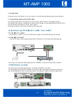
Страница 49: ...n Bitte beachten Sie dass die Last Impedanz nicht niedriger als die Nenn Impedanz ist MT AMP 1000 ic audio GmbH Boehringerstraße 14a D 68307 Mannheim Germany Fon 49 0 621 77096 0 Fax 49 0 621 77096 26 E Mail info ic audio com www ic audio com DT 21 19 0 8 Ohm 70V 100V Ausgang Der 0 8 70V 100 Ausgang kann nur verwendet werden wenn die anderen Zonen Ausgänge nicht kOhm verwendet werden ic audio ...
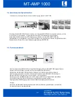
Страница 50: ...1000 durch einen externen Schalter in Betrieb zu nehmen Um diese Funktion zu nutzen muß der MT AMP 1000 Netzschalter auf der Position OFF stehen 21 Batterieanschluss Notstrom Batterie Zwei 12V Batterien können mit dem 24V DC Anschluss verbunden werden Die Batteriespannung kann bei Ausfall des Stromnetzes die Stromversorgung des MT AMP 1000 übernehmen Hinweis Bitte die richtige Polarität bei Anschl...

Страница 51: ...Ende der Kabellänge angeordnet Werden sie auf die Länge verteilt so sind gegebenenfalls größere Längen möglich aber insgesamt nicht mehr als 500 Meter 1 Sprechstelle MT PM 06 ohne Erweiterung 500 Meter 1 Sprechstelle MT PM 06 mit 4 Erweiterungen MT PM K12 500 Meter 6 Sprechstellen MT PM 06 ohne Erweiterung 400 Meter 6 Sprechstellen MT PM 06 mit 4 Erweiterungen MT PM K12 100 Meter Bei größeren als ...

Страница 52: ...ic audio GmbH Boehringerstraße 14a D 68307 Mannheim Germany Fon 49 0 621 77096 0 Fax 49 0 621 77096 26 E Mail info ic audio com www ic audio com DT 24 MT AMP 1000 ic audio 23 ...
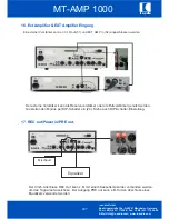
Страница 53: ...ic audio GmbH Boehringerstraße 14a D 68307 Mannheim Germany Fon 49 0 621 77096 0 Fax 49 0 621 77096 26 E Mail info ic audio com www ic audio com DT 25 MT AMP 1000 ic audio 24 ...
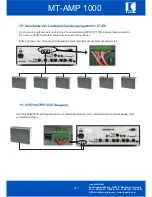
Страница 54: ...minal Power In 1V 600Ohm unbalanced RCA terminal Callstation 1V RJ45 terminal TEL EMEG 100mV 600Ohm balanced Input Wall Control Panel 1V RJ45 terminal 100V Input 100V balanced Input Ext Amp in 100V input REC Out 1V unbalanced RCA Jack PRE Out 1V unbalanced RCA Jack Ext Amplifier XLR out 1V balanced XLR Jack MOH 0 8Ohm 8Ohm 1W unbalanced MOH 600Ohm 600Ohm output 1Vrms balanced Direct Output 100V 70...

Страница 55: ... ON OFF MIC Pri 2 DIP switches to select 4 different priority modes DIP Switch Setting Chime 2 DIP switches to set 4 different chime modes MIC 1 6 Rotary Source AUX 1 3 Rotary Vol Control Master Rotary VOX Mute Level Rotary TEL Level Rotary MOH Level Rotary Level Control Chime Level Rotary Zone Output Att Zone 1 6 Rotary 6 steps ZONE 1 6 6 tact switches ALL 1 tact switch Remote Source AUX1 3 1 tac...

Страница 56: ...ic audio to make people listen ic audio GmbH Boehringerstraße 14a D 68307 Mannheim Germany Fon 49 0 621 77096 0 Fax 49 0 621 77096 26 www ic audio com E Mail info ic audio com ...

Отзывы: