background image

DANGER

<1-14> Switch off printer power and unplug the printer power cord before connecting or disconnecting a
communication port, a teleport, or other attachment connector.

e61a9054

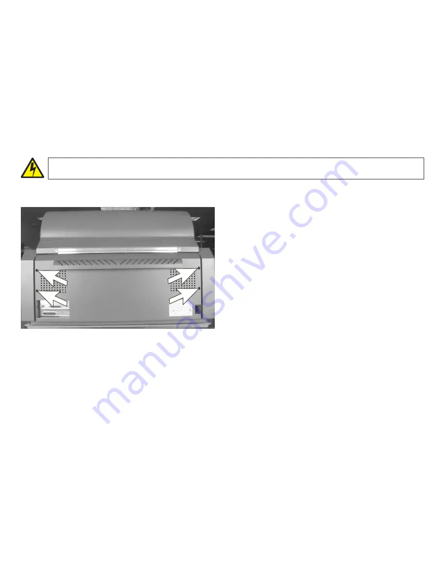
1. Turn off the printer and disconnect the power cord from the

rear of the printer.

2. Disconnect the attachment cable from the rear of the printer.

Disconnect the self-terminating T-connector from the printer
attachment card. Do not disconnect the host
communication-cable from the printer T-connector.

3. Loosen, but do not remove, the 4 shouldered screws that

hold the rear cover.

4. Partially open the top cover to approximately 45°.

5. Slide the rear cover up and remove it from the 4 shoulder

screws.

Chapter 5. Removals, service checks and adjustments

193

Содержание V03

Страница 1: ...IBM 4247 Model V03 Serial Matrix Impact Printer IBM 4247 Model V03 Maintenance Information Part Number 75P1301 IBM...

Страница 2: ...ition applies to release one of IBM 4247 Model V03 Maintenance Information and to all subsequent releases and modifications until otherwise indicated in new editions Copyright International Business M...

Страница 3: ...ter 3 Wiring diagrams Chapter 4 Locations Chapter 5 Removals service checks and adjustments Chapter 6 Parts catalog Chapter 7 Preventative Maintenance Appendix A Printer configuration Appendix B Suppl...

Страница 4: ...receptacle 8 Electrical safety and portable power strip receptacles 8 Connecting or disconnecting a communication port a teleport or an attachment connector 9 Servicing during an electrical storm 9 Sa...

Страница 5: ...n IBM 4247 Model V03 Safety Information G544 5862 Example of a Danger notice DANGER 1 10 Hazardous voltages are present Do not touch the pins or sockets of the power receptacle Caution hazard level Th...

Страница 6: ...ng laboratory indicates that the product is designed and manufactured in accordance with national requirements intended to minimize safety hazards IBM equipment meets a very high standard of safety in...

Страница 7: ...ot touch any components pins or connectors If possible keep one hand on the frame while you are installing or removing an ESD sensitive part v Do not place an ESD sensitive part on anything that can p...

Страница 8: ...d and plug Ensure that you have the correct power cord and plug Use this cord and plug only with an approved correctly installed power receptacle Electrical safety and portable power strip receptacles...

Страница 9: ...nd unplug the printer power cord before connecting or disconnecting a communication port a teleport or other attachment connector Servicing during an electrical storm DANGER 1 13 Do not connect or dis...

Страница 10: ...nections can cause serious electrical shock v Mechanical A missing safety cover or shield is hazardous Moving parts such as gears shaft and pulleys are hazardous v Chemical Use only approved cleaning...

Страница 11: ...g contamination water or other liquids or signs of fire or smoke damage 9 Check for worn frayed or pinched cables Performing a power receptacle safety check A trained service representative or a quali...

Страница 12: ...trical outlet and any temporary power tap must meet the requirements as stated in 4247 Model V03 nominal ac input power requirements Attention Inform the customer if the voltages are not within the co...

Страница 13: ...ensor Front Tractor paper present sensor Rear Tractor paper present sensor 38V 5V Front Tractor paper run sensor Rear Tractor paper run sensor Control Panel Assembly Attention Light GND 38V Parallel I...

Страница 14: ...Ground path illustrations e61a6003 Left Side Adapter Card AC Input Right Side Right Side Printer to Metal Table 1 2 4 5 3 6 1 6 See previous page for wiring diagram Safety and environmental notices 14...

Страница 15: ...ecycle their equipment when it is no longer needed IBM offers a variety of programs and services to assist equipment owners in recycling their IT products Information on these product recycling offeri...

Страница 16: ...he second path is an optional feature The printer operator panel is common with the Models 001 002 and 003 and includes the same full function full size 2 line by 40 character display making messages...

Страница 17: ...e second optional tractor is the front tractor and the base tractor becomes the rear tractor Print qualities Fast Draft is a new print quality for the IBM 4247 Model V03 that is available only on the...

Страница 18: ...acter cell size dots Fast Draft 45 72 9 9 DP 60 72 12 9 DP Text 100 144 20 9 NLQ 100 144 20 18 4247 Model V03 differences and commonality with earlier models Adjustments All 4247 Model V03 adjustments...

Страница 19: ...s were found on earlier models Flash memory download and printer microcode file The 4247 Model V03 flash download code is a single file that supports all printer attachment configurations The download...

Страница 20: ...so have a 12 pin ribbon cable plugged into it This connector and cable are not used by the 4247 Model V03 18 wire print head AFTA service check and adjustment procedures for the V03 are common with ea...

Страница 21: ...S544 5861 75P0513 IBM 4247 Model V03 Programming s Reference S544 5864 IBM 4247 Model V03 User s Guide S544 5863 v IBM 4247 Model V03 Maintenance Information CD SK2T 9360 75P0796 Contents of CD ROM T...

Страница 22: ...Model V03 Quick Setup Guide English Danish Dutch Finnish Swedish S544 5860 75P0514 v IBM 4247 Model V03 Quick Setup Guide English Arabic S Chinese Hungarian Polish Russian Turkish S544 5861 75P0513 P...

Страница 23: ...cover interlock 61 MAP 0190 Form feed problems 62 MAP 0200 55 AFTA errors 73 MAP 0210 Intermittent failures 75 MAPs reference tables 77 Reference table 1 error messages 77 Reference table 2 no printe...

Страница 24: ...Reference table 8 ribbon lift and 26 pin cable connectors 93 Chapter 1 Diagnosing problems 24...

Страница 25: ...quickly identify problem areas v The normal place to start a service call in these MAPs is at MAP 0100 START OF CALL MAP 0100 START OF CALL This MAP sends you to a Field Replaceable Unit FRU or to an...

Страница 26: ...le the MAPs are written so that No is the error path answer v Verify repair or exchange FRU When a card or a cable is identified as the failing FRU reseat it and verify that the same problem remains I...

Страница 27: ...st and diagnostic IPDS Intelligent Printer Data Stream SCS SNA systems network architecture character string FRU Field replaceable unit ESD Electrostatic discharge NPS Network printer server ACGA Atta...

Страница 28: ...No 1 Has the Customer completed the Problem Solving Procedures in the IBM 4247 Model V03 User s Guide Go to step 2 Attempt recovery using the Problem Solving Procedures in IBM 4247 Model V03 User s G...

Страница 29: ...Reference table 2 no printed characters and perform the action suggested Go to step 4 4 Is the problem print quality Find the description of the failure in Reference table 3 print quality failures an...

Страница 30: ...figuration Notes 1 This is the correct MAP for a Model V03 with parallel only or a Model V03 with a serial attachment card 2 Printing in hexadecimal code is available to aid service personnel and prog...

Страница 31: ...es through the options found by pressing the Menu key the Configuration Menu should appear Table 2 Configuration Menu Parallel and Serial Configuration This is an indication that the printer recognize...

Страница 32: ...a teleport or any other connector during an electrical storm DANGER 1 14 Switch off printer power and unplug the printer power cord before connecting or disconnecting a communication port a teleport o...

Страница 33: ...or your parallel or serial attachment Parallel INTERFACE TYPE SELECT IN EMULATION MODE CHARACTER SET PRINT LANGUAGE Serial INTERFACE TYPE DATA BITS BAUD RATE PARITY PACING PROTOCOL CONNECTION TYPE EMU...

Страница 34: ...card see Attachment cards serial twinax LAN coax or Install a new logic board see Logic board or Install a new host cable Run T D in Automatic Mode to verify correct printer operation see Running the...

Страница 35: ...the test and diagnostic T D programs 6 Do you have the parallel loop back connector PN 08H7269 for this printer Go to step 7 Install a new logic board see Logic board or Install a new host cable Run T...

Страница 36: ...connection Logic board includes parallel attachment Note Printing in hexadecimal code is available to aid service personnel and programmers for host program debug Press the Stop key the Hex Print key...

Страница 37: ...Loosen the screws and reseat the attachment card b Replace the attachment card see Attachment cards serial twinax LAN coax or Replace the interposer connector see Attachment card guide assembly with...

Страница 38: ...ed 5 Press the Test key The message 4247 OPERATOR TESTS appears 6 Press the Micro key until the Printer Configuration test is displayed below 4247 OPERATOR TESTS 7 Press the Enter key and wait for the...

Страница 39: ...actions to find the message Perform the action indicated 5 Do you have the parallel loop back connector PN 08H7269 for this printer Go to step 6 Install a new logic board see Logic board or Install a...

Страница 40: ...al storm DANGER 1 14 Switch off printer power and unplug the printer power cord before connecting or disconnecting a communication port a teleport or other attachment connector Table 6 MAP 0122 LAN ca...

Страница 41: ...Reference table 6 network server problems LAN attachment card before going to the next item Is the problem corrected Run T D in Automatic Mode to verify correct printer operation see Running the test...

Страница 42: ...supply the printer powers the unit through 5 V dc on pin of the printer parallel attachment connector 2 NPS device part numbers 30H4082 30H4083 30H4055 cannot be powered by the printer and require an...

Страница 43: ...n Reference table 5a LED and test page problems External NPS Is the problem corrected Run T D in Automatic Mode to verify correct printer operation see Running the test and diagnostic T D programs Go...

Страница 44: ...emove the paper bail c Rotate the upper feed roller by hand Do the failing tractor pin feed belts move Go to step 4 Go to step 2 2 Perform the Tractor asm service checks Is the service check OK Go to...

Страница 45: ...or Install a new tractor assembly cable Run T D in automatic mode to verify correct printer operation see Running the test and diagnostic T D programs or Install a new paper drive motor see Paper feed...

Страница 46: ...s it visible between the printhead and the platen Go to step 2 Probable forms loading problem see MAP 0130 No paper movement 2 Are you trying to load black back forms Go to step 3 Go to step 4 3 Black...

Страница 47: ...he Stop key to make the printer Not Ready 8 Press the Load Eject key Is there a false paper path sensor message Run T D15 and verify correct sensor operation If not OK v Install a new logic board see...

Страница 48: ...rner on the leading edge of the forms is catching in printhead mask mask damaged Carriage belt tension is incorrect Carriage belt clamp is loose Carriage motor is defective mounting hardware Carriage...

Страница 49: ...er operation see Running the test and diagnostic T D programs 3 When the print wires are too close to the platen they can cause printhead drive problems Perform the AFTA service check see Standard AFT...

Страница 50: ...resistance checks to measure the resistance of the thermal sensor Measure between pins 5 and 6 on the printhead 26 pin connector Is the resistance 1000 ohms 6 60 ohms Go to step 6 Install a new print...

Страница 51: ...n page 232 Install a new carriage motor see Carriage drive motor assembly and fan or Install a new logic board see Logic board or Install a new encoder board see Encoder board or Install a new encoder...

Страница 52: ...not install a power supply with a different part number Symptom explanation Suspected FRUs causes Display blank and keys do not operate Power failure Power supply Power cord Logic board Operator panel...

Страница 53: ...ce Low 90 120 137 50 60 Hz High 180 220 264 50 60 Hz Is the voltage correct Go to step 2 Have the customer repair the voltage problem Run T D in automatic mode to verify correct printer operation see...

Страница 54: ...supply board f Disconnect the power supply cable to the logic board g Plug the power cord to the printer then to the power source h Turn on the printer i Measure the power supply connector voltages M...

Страница 55: ...board locations v Attachment card if present v Printhead ribbon cables v Sensor cable v Tractor cable asm v AFTA motor v Paper feed motor v Carriage motor v Ribbon motor d Turn on the printer Does the...

Страница 56: ...t steps 1 2 and 3 connecting the following one at a time until the failing load is found v Attachment card if present v Printhead ribbon cables v Sensor cable v Tractor cable asm v AFTA motor v Paper...

Страница 57: ...ting Table 12 MAP 0160 Ribbon feed and ribbon lift Step Questions Actions Yes No 1 The following items are possible causes for ribbon feed or lift failures v Ribbon installed incorrectly v Ribbon cart...

Страница 58: ...D programs Go to step 4 4 Perform the ribbon service check see Ribbon feed and ribbon lift service check Is the service check OK Go to step 5 Repair as needed 5 Ensure that a ribbon is installed Run T...

Страница 59: ...de to verify correct printer operation see Running the test and diagnostic T D programs Install a new ribbon drive motor see Ribbon drive motor Run T D in automatic mode to verify correct printer oper...

Страница 60: ...ors Is the resistance 5 ohms or less for all measurements Put back the printhead Install a new logic board see Logic board or Install new printhead cables Run T D in automatic mode to verify correct p...

Страница 61: ...cover magnet Located near the left side of the operator panel when the cover is closed v Operator panel cable and connectors Are the parts OK Install a new operator panel see Operator panel or Instal...

Страница 62: ...CTOR 020 FORMS JAMMED REAR TRACTOR 032 FORMS JAMMED TIMEOUT 088 INVALID PAPER SOURCE 099 FORMS JAMMED Forms Jam Forms Stick Together Debris or unwanted paper in forms path Tractor assembly Mechanical...

Страница 63: ...her the printer sensed that the forms have stopped processing through the printer or the printer sensed forms are present when no forms were expected The messages 002 and 020 are sensed by the tractor...

Страница 64: ...ge the amount of chad to be excessive advise the customer to v Frequently clean out the chad v Ask the forms supplier to reduce the chad Run T D in automatic test mode to verify correct printer operat...

Страница 65: ...ck if the red LED is now lighted If the red LED is still not lighted check that the small flat ribbon cable in the tractor is fully connected to the tractor motor Check if the red LED is now lighted I...

Страница 66: ...front and rear push forms paths e Forms tension between the left and right tractors is properly adjusted Left Margin Left Margin Right Margin Right Margin Correct Incorrect f Forms meet specification...

Страница 67: ...tached Note If you suspect lower plastic shield damage remove the screws to remove the plastic shield and inspect it for damage Shield e90alocg v Locate and remove any paper debris label debris or lab...

Страница 68: ...move the ribbon Remove the forms Move the printhead as far to the right as possible Is there spring tension holding the paper bail plastic shield open approximately 10 mm 0 39 in Go to step 11 Install...

Страница 69: ...or asm service checks Is the service check OK You have completed this procedure Repair as needed Run T D in automatic mode to verify correct printer operation see Running the test and diagnostic T D p...

Страница 70: ...s the correct way to mount the forms The 099 message occurred because the printer sensors were already sensing forms in the path when the customer tried to load forms Go to step 17 17 Examine the sens...

Страница 71: ...forms Run T D15 including performing a sensor tune and verify correct sensor operation If not OK v Install a new logic board see Logic board v If the printer is still failing after the logic board ha...

Страница 72: ...fter the logic board has been changed install a new sensor assembly cable see Sensor cable assembly Run T D in automatic mode to verify correct printer operation see Running the test and diagnostic T...

Страница 73: ...r poor connection Mechanical parts damaged or binding Printhead defective Logic board defective CAUTION The printhead may be hot Wait for it to cool down Table 15 MAP 0200 55 AFTA errors Step Question...

Страница 74: ...uctors 11 and 12 from end to end Inspect the contacts at the ends of the cable for delamination and other damage Are the cables OK Go to step 3 Install new printhead cables and reassemble the printer...

Страница 75: ...l v System error log host system information v Online problem operator identified v System identified problem v Power on failure cold start v Long run time failures hot overheated An online program ca...

Страница 76: ...heck Set the meter to the lowest resistance scale and measure for 0 1 ohms or less between the ground pin of the power cord and the following parts Attachment Ensure that the printer is not operated w...

Страница 77: ...MMED FRONT TRACTOR CLEAR JAM AND RELOAD FORMS Jam detected at the front tractor sensor See MAP 0190 Form feed problems 005 MARGIN ERROR ADJUST MARGIN OR LINE LENGTH Left margin incorrect Press Stop th...

Страница 78: ...0121 Parallel with twinax or coax attachments on page 36 017 COMMUNICATIONS CHECK Twinax interface only Line parity error detected See MAP 0121 Parallel with twinax or coax attachments 020 FORMS JAMME...

Страница 79: ...FORMS TIMEOUT LOAD FORMS Coax interface only False 001 END OF FORMS condition exceeded 60 seconds Forms do not load when Load Eject is pressed No forms movement See MAP 0130 No paper movement 032 FORM...

Страница 80: ...AT INPUT AND PRESS EJECT Coax interface only 092 FANFOLD EJECT condition exceeded 60 seconds Tear off paper before entering the printer and press Eject to allow operation to complete 050 MACHINE CHECK...

Страница 81: ...bris is blocking the printhead encoder 2 Ensure all logic board connectors are connected 3 See MAP 0140 Printhead drive 055 MACHINE CHECK AFTA failure Turn off and then turn on the printer If message...

Страница 82: ...lift 096 COVER OPEN False Message The cover open sensor has detected an error See MAP 0180 Top cover interlock 097 FUNCTION NOT AVAILABLE MENU LOCKED The operator panel has been locked This means the...

Страница 83: ...If message remains see MAP 0190 Form feed problems 201 NO ATTACHMENT CARD FOUND SEE USER S GUIDE A serial LAN coax or twinax attachment card was not found during the current power on but was previous...

Страница 84: ...ly and the interposer connector for damage Replace if necessary see Attachment card guide assembly with the interposer connector 3 If error reoccurs replace logic board see Logic board 220 SERIAL DSR...

Страница 85: ...eck that the ribbon is seated correctly 2 See Standard AFTA service check and adjustment 3 See MAP 0160 Ribbon feed and ribbon lift No print from serial parallel or both attachments but print test is...

Страница 86: ...Main paper drive check and adjustment 4 See Printhead drive service check 5 Check for excessive ribbon inking Smearing or smudging 1 See MAP 0160 Ribbon feed and ribbon lift 2 See Main paper drive che...

Страница 87: ...EDs are off and keys do not operate 1 Ensure that the operator panel cable is connected correctly at both ends 2 See MAP 0150 Power supply 3 Install a new operator panel see Operator panel Buzzer soun...

Страница 88: ...damage See MAP 0190 Form feed problems Reference table 5 LED and test page problems LAN attachment card Symptom Probable cause Action LAN attachment not shown on operator panel display No communicati...

Страница 89: ...p test passes replace the LAN card 6 If the parallel port wrap test fails replace the logic board Test page prints with error messages Internal errors 1 NVRAM E1 or NVRAM E2 a Disconnect the power cab...

Страница 90: ...ff on the printer LAN must be shown on the display 2 If the problem continues replace the LAN card see Attachment cards serial twinax LAN coax Test page will not print 1 Check that parallel configurat...

Страница 91: ...Check for 5 V dc on pin 18 of the printer parallel port pin numbers on connector 3 If 5 Vdc is not present install a new logic board see Logic board 4 Go to Table 6 step 2 Reference table 6 network se...

Страница 92: ...ration Including IP address gateway address and subnet mask 3 Have the customer check physical network cabling LAN card communicates with host but printer does not print Data stream problem 1 Have the...

Страница 93: ...15 is the idle control input signal from the logic board and will measure 0 V dc when the power supply is disconnected from the logic board 2 When connected to the logic board pin 15 will be 4 8 to 5...

Страница 94: ...Table 19 Connectors continued Ribbon Lift Connector 26 Pin Connector Pin 4 Pin 26 See Ribbon lift motor wiring for details on the location of the pins on the connector Chapter 1 Diagnosing problems 94...

Страница 95: ...05 T D04 Microcode test 105 T D05 Serial card attachment test 106 T D07 Sensor tune ribbon feed and lift motors 106 T D08 AFTA calibrate test 107 T D09 First printing line adjustment test 110 T D10 Bi...

Страница 96: ...T D37 Adapter board digital test 125 T D38 Adapter board analog test 125 T D error messages and actions 127 Chapter 2 Diagnostics 96...

Страница 97: ...ESTS 7 Press the Enter key and wait for the test to finish 8 Press the Cancel Print key to exit test mode Printing the firmware part number and version levels 1 Power off the printer 2 Load the printe...

Страница 98: ...D s are lighted 3 Press the Test key The message 4247 OPERATOR TESTS appears and the Online LED goes out 4 Press the Micro key until the Printer Configuration test is displayed below 4247 OPERATOR TES...

Страница 99: ...following procedure to print or clear the error log or to print usage metrics 1 Select the paper path from which you are going to print the error log or usage metrics 2 Load the printer with at least...

Страница 100: ...or v Press the Cancel Print key to return to online Ready Figure 1 shows a sample printout of the Models 001 002 and 003 error log The asterisk indicates the most recent error Figure 2 on page 101 sh...

Страница 101: ...refers to loop back connectors needed for T D03 parallel interface If the connector is not available the test can be bypassed as described in T D03 Parallel attachment test Attention Power off the pr...

Страница 102: ...orward scrolling only TEST AND DIAGNOSTIC STARTUP SINGLE YES NO a Press the Line Feed key to select YES The following message will be displayed T DXX Microcode Test RUN TEST YES END NO b To scroll to...

Страница 103: ...error is detected an error message will be displayed TDXX FRU X X PRESS A KEY c For a description of error messages go to T D error messages and actions d If all the tests run OK the following messag...

Страница 104: ...ge is displayed go to T D error messages and actions The test completed successfully if the display advances to the next test number T D02 Operator panel led and key test Display T D02 Operator Panel...

Страница 105: ...arallel loop back connector PN 08H7269 needs to be installed for this test Note If the loop back connector is not installed an error message will be displayed To bypass this message press any key then...

Страница 106: ...RS 422 loop back connector If a loop back connector is not installed an error message will be displayed T D05 Serial Attachment Test RUN TEST YES END NO 1 Install RS 232 connector 2 Press Line Feed k...

Страница 107: ...the test If either motor fails go to MAP 0160 Ribbon feed and ribbon lift 6 If an error message is displayed go to T D error messages and actions 7 The test completed successfully if the display advan...

Страница 108: ...T D08 see Running T D08 on page 109 3 Use STORE NO 4 Move the value to x to increase the gap and x to decrease the gap This adjustment is described in Standard AFTA service check and adjustment on pag...

Страница 109: ...he top of the character 5 Inspect the printhead cable for damage and a poor connection at the printhead Replace the cable if indicated 6 If the cable is OK replace the printhead Running T D08 v Press...

Страница 110: ...bon The print should appear dark Press the Micro key to bypass this message T D09 First printing line adjustment test This test allows you to adjust the first print line for the rear base forms path a...

Страница 111: ...be printed on the first printing line and then the paper will feed to a position for viewing The Es should be completely on the paper The top of the Es should be approximately 1 mm 0 04 in below the p...

Страница 112: ...ted successfully if the display advances to the next test number If the rear is OK the test progresses to Fanfold Front Adj T D10 Bidirectional adjustment test Note This test allows the bidirectional...

Страница 113: ...ottom row of Is to the left The value changes on the operator panel display 10 Press the Form Feed key to repeat step 6 11 If an error message is displayed go to T D error messages and actions 12 The...

Страница 114: ...nt Test LOAD PAPER 6 Install fanfold paper in the rear tractor assembly 7 Press the Load Eject key 8 A line of Xs will be printed on the first print line The paper will feed to the tear off bar for vi...

Страница 115: ...paper up or press the Start key to move the paper down The range is 128 to 127 Each unit is approximately 0 2 mm 0 008 in When the tear off is correct go to the next step Form Perforation Line Tear Ed...

Страница 116: ...test number T D12 Fanfold form printout test Note Use this test to check print quality print wires printhead wire shifter 18 wire printhead only carrier movement paper feed line skew and bidirectional...

Страница 117: ...3 Top Cover Interlock Test RUN TEST YES END NO 2 Press the Line Feed key The following message will display T D13 Top Cover Interlock Test OPEN COVER 3 Open the top cover If you do not open the cover...

Страница 118: ...ing message will display T D14 NLQ Printhead Mode Test NLQ 9 BIDIR YES NO 4 In this mode the printhead will print NLQ by using 9 wires and two passes per line in bidirectional mode 5 To select this mo...

Страница 119: ...performing a sensor tune at this time T D15 Sensor Test SENSOR TUNE YES NO 3 To perform a sensor tune press the Line Feed key Press the Start key to skip to step 4 without performing a Sensor Tune 4...

Страница 120: ...HRESHOLD YES NO This part of the test is intended for use by Product Engineering and allows the user to examine internal sensor threshold values stored in NVRAM 7 Press the Start key to skip to step 8...

Страница 121: ...intended for use by Product Engineering and allows the user to examine sensor output voltages 9 Press the Start key to skip to step 10 on page 122 Press the Line Feed key to enter If the front tracto...

Страница 122: ...o go to step 10 10 The following displays T D15 Sensor Test REPEAT TEST YES NO Press the Line Feed key to restart from path status step 2 on page 119 Press the Start key to end the test NOTE The follo...

Страница 123: ...e test completed successfully if the display advances to the next test number T D32 Adapter board EPROM test This test checks the attachment card and the flash memory module Display T D32 Adapter Boar...

Страница 124: ...essage is displayed go to T D error messages and actions The test completed successfully if the display advances to the next test number T D35 Adapter board shared RAM test This test checks the attach...

Страница 125: ...Note The message TEST RUNNING will display during the test If an error message is displayed go to T D error messages and actions The test completed successfully if the display advances to the next te...

Страница 126: ...actions The test completed successfully if the display advances to the end of diagnostics message The test then loops back to T D01 Pressing End displays the following message TEST DIAGNOSTIC END 3 P...

Страница 127: ...Hardware Match Error Replace the logic board see Logic board TD 1 FRU 2 2 Microcode error Replace the logic board see Logic board TD 2 FRU 1 X Operator panel failure 1 This error can occur if a key i...

Страница 128: ...al a Replace the logic board see Logic board b Replace the sensor cable assembly see Sensor cable assembly TD FRU 2 12 Ribbon sense failure 1 Replace the ribbon drive motor see Ribbon drive motor 2 Re...

Страница 129: ...e the logic board see Logic board 4 Replace the tractor cable assembly TD FRU 2 17 Front tractor sense failure 1 Clear front feed paper jam front tractor path 2 See Tractor asm service checks 3 Replac...

Страница 130: ...hing memory and Attachment cards serial twinax LAN coax on page 201 TD 33 FRU 7 33 Attachment card DRAM failure Replace the attachment card see Attachment cards serial twinax LAN coax TD 34 FRU 7 34 A...

Страница 131: ...X Can be any number This error message will display if a loop back connector is not installed Press the Form Feed key to bypass this test If a loop back connector is installed perform the recommended...

Страница 132: ...135 AFTA motor wiring 136 Carriage motor wiring 137 Operator panel cable wiring 138 Paper feed motor wiring 139 Parallel connector 140 Ribbon feed motor wiring 141 Ribbon lift motor wiring 142 Sensor...

Страница 133: ...is connected to the logic board by a 22 pin cable a 26 pin cable and a 12 pin cable The 4247 Model V03 does not use the 12 pin cable Ribbon Lift Connector Pin 1 26 Pin Connector Pin 1 22 Pin Connecto...

Страница 134: ...Wire 2A coil 5 Thermal sensor ground 6 Thermal sensor 7 Wire 3A coil 8 Wire 3A coil 7 Wire 2B coil 8 Wire 2B coil 9 Wire 4A coil 10 Wire 4A coil 9 Wire 3B coil 10 Wire 3B coil 11 Wire 5A coil 12 Wire...

Страница 135: ...in Connector Pin 1 Encoder Connector Pin1 12 Pin Connector Not Used 18 Wire Printhead e61a9045 22 PIN CABLE Print Head e61a9047 26 PIN CABLE Logic Board Print Head e61a9048 12 Pin connector and cable...

Страница 136: ...r connects directly to the logic board Resistance measurements Attention Allow the paper feed motor to cool before taking resistance measurements Pins Resistance Temperature 1 red to 2 brown 19 Ohms 1...

Страница 137: ...2 01 INSERT SIDE P 01 01 02 03 RED LIGHT BLUE BLACK e61a9046 Resistance measurements Attention Allow the carriage motor to cool before taking resistance measurements Phase Resistance Temperature 1 bla...

Страница 138: ...Operator panel cable wiring Chapter 3 Wiring diagrams 138...

Страница 139: ...motor connects directly to the logic board Resistance measurements Attention Allow the paper feed motor to cool before taking resistance measurements Pins Resistance Temperature 1 yellow to 2 red 1 3...

Страница 140: ...r 13 slct Printer selected 14 auto feed xt Automatic line feed on EOL 15 unused 16 logic ground Logic ground 17 chassis ground Chassis ground 18 5 V dc NPS 540 P N 30H4052 power 19 30 ground Ground 31...

Страница 141: ...ds go through the print head cables to the logic board Resistance measurements Attention Allow the paper feed motor to cool before taking resistance measurements Pins Resistance Temperature 1 green to...

Страница 142: ...nnects to the printhead and the printhead cable connects to the logic board Resistance measurements Attention Allow the paper feed motor to cool before taking resistance measurements Pins Resistance T...

Страница 143: ...r The two paper presence sensors are reflective type sensors 1 2 3 4 13 14 15 16 17 18 19 20 A K C E A K C E A K C E 1 1 2 2 3 3 RIBBON MOTION FANFOLD FRONT PAPER PRESENCE FANFOLD REAR PAPER PRESENCE...

Страница 144: ...Tractor assembly cable wiring Chapter 3 Wiring diagrams 144...

Страница 145: ...26 Pin Connector Operator Panel Attachment Connector Tractors Sensors Paper Feed Motor Power Supply Connector F2 not a FRU F1 not a FRU Power Switch not a FRU Carriage Fan Board Fan AFTA Motor Ribbon...

Страница 146: ...rd AFTA service check and adjustment 152 Bidirectional Printing 160 Service check 160 Adjustment 160 Carriage drive belt 161 Service check 161 Adjustment 162 Carriage support shaft 163 Service check a...

Страница 147: ...menclature 192 Covers 192 Rear cover and top cover asm 192 Left or right side cover 197 Logic board and power supply metal protector 198 Top access cover 199 Paper conveyor 200 Attachment cards serial...

Страница 148: ...otor drive belt 227 Platen assembly 228 Power supply 230 Printer mechanical assembly 231 Printhead 232 Printhead mask 234 Ribbon drive motor 235 Ribbon lift motor 237 Upper feed roller shaft assembly...

Страница 149: ...allows the printer to maintain a consistent distance between the printhead and the face of the forms Maintaining this distance or gap allows the printer to produce correct print darkness properly feed...

Страница 150: ...ice check and adjustment procedures see Standard AFTA service check and adjustment to understand some problems Follow these steps to perform the Quick AFTA service check 1 Check that the print head is...

Страница 151: ...place a magnet on the upper left corner of the operator panel to disable the cover interlock a Setup Install the front tractor the bail assembly and a new or nearly new ribbon Verify that the value in...

Страница 152: ...Use estimate A for Print Gap If estimate B is greater than estimate A by more than 0 5 wheel number Use estimate A 0 5 for print gap If estimate B is LESS than estimate A the print needles are worn do...

Страница 153: ...service This check verifies the position of the wheel and the manual operation of the AFTA mechanism Use the wheel as an indicator as you adjust the distance between the print needles and the platen E...

Страница 154: ...se you will notice clicking at the frame when you grasp the carriage shaft and attempt to move it up and down When you grasp and attempt to move it the carriage shaft is correctly adjusted if it turns...

Страница 155: ...pect the printhead cable for damage and a poor connection at the printhead Replace the cable if indicated Power On Check Perform this check only after completing the Power Off Check Note To view the A...

Страница 156: ...ingle part forms 2 Set the operator panel menu item AFTA 0 3 With loose forms back fold the beginning of the forms along a left to right perforation 4 Mount these forms onto the tractor pins The print...

Страница 157: ...If any of the needles are not functioning or if the xxB line segments are not lower than the xxA line segments replace the printhead Line 11 If you notice ink smearing on a printout such as with T D1...

Страница 158: ...1 If the FIXED 1 sample is dark the FIXED 2 sample is also dark and the FIXED 3 sample is light gray you should create a FIXED 4 sample The FIXED 4 sample should appear light and exhibit some missing...

Страница 159: ...If you cannot locate the white dot you will use a 0 3 mm 0 012 in feeler gauge in the next step 2 Check the gap between the printhead needles and the platen using one of the feeler gauges 3 If the res...

Страница 160: ...D12 to print NLQ characters If the vertical bars on the characters are not aligned perform the adjustment As an aid in evaluating the print see Print quality service checks and Table 24 Adjustment 1...

Страница 161: ...To accurately measure the tension it is critical for the raised surfaces of the teeth to align as shown in Figure 6 The correct force required to bring the top of the belt into contact with the botto...

Страница 162: ...28 2 56 lb is required to push the upper half of the belt center between the printhead and the left side frame to touch the bottom half of the belt 3 Tighten the lock nut and check the adjustment agai...

Страница 163: ...ed to the middle of sector 1 The correct difference in the gap between the left and right ends is 0 08 mm 0 003 in 4 Using pliers rotate the eccentric bushing until a minimum difference between the le...

Страница 164: ...Chapter 5 Removals service checks and adjustments 164...

Страница 165: ...e T D program in single test mode v See Running the test and diagnostic T D programs 2 Scroll to T D09 Paper feed belt Service check 1 Turn off the printer 2 Remove the printer covers see Service posi...

Страница 166: ...off the printer 2 Remove the printer covers see Service position 3 Inspect the following parts for wear damage or binds Hand cycle the paper feed mechanism Install new parts as needed Note Remove the...

Страница 167: ...en the carriage is at the right side The paper bail plastic shield should be held open approximately 10 mm 0 4 in by spring tension e Inspect the following parts for wear damage or binds Install new p...

Страница 168: ...cause paper feed failures Ensure that they are correct a Standard AFTA service check and adjustment b Sensor service checks c Paper feed belt 6 Clean the following parts with isopropyl alcohol PN 2155...

Страница 169: ...r failure to feed problems Front and rear push path check 1 Locate and remove from the forms path torn pieces of paper or other foreign material that can cause forms jams 2 Inspect the following parts...

Страница 170: ...he information in Table 23 to analyze the printout in Table 24 Table 23 Print quality tests and actions fanfold Line Description Action if failure 1 Skew test in draft mode The line should print paral...

Страница 171: ...see Running the test and diagnostic T D programs on page 101 5 Paper feed test Prints three lines of alternating line segments and spaces The top and bottom lines are printed first The middle line is...

Страница 172: ...ll a new printhead See Printhead 2 Install a new logic board see Logic board 3 Install new printhead cables 10 Printhead drive test Prints 19 lines The left margin should be even See Printhead drive s...

Страница 173: ...Table 24 Print quality sample 1 2 3 Chapter 5 Removals service checks and adjustments 173...

Страница 174: ...strip for cleanliness damage or a loose mounting E61a9107 Figure 12 Encoder sensor and encoder strip 5 Inspect the carriage motor and pulley for wear damage binds or looseness Ensure that the 4 screw...

Страница 175: ...ey must be free turning Slide the carriage throughout the full travel and ensure that the pulley turns v Carriage drive belt clamp must properly mesh with the belt teeth and be fastened tightly Replac...

Страница 176: ...carriage support shaft bushing If the large carriage shaft is coated replace the carriage assembly 8 Verify that the carriage shaft retainers and the sheet metal wear surfaces are installed correctly...

Страница 177: ...s of the mask remove it from the carriage by unscrewing the 2 screws holding the mask on to the carriage Replace the printhead mask 10 Inspect for wear or damage the plastic shields that cover the pla...

Страница 178: ...11 Return to the step that sent you here Lower Plastic Shield Upper Plastic Shield Paper Bail Figure 16 Plastic shields Viewed from top Chapter 5 Removals service checks and adjustments 178...

Страница 179: ...ce the ribbon cartridge if you locate a problem such as a ribbon that binds or is folded over 3 Inspect the left ribbon bracket for wear damage or binds Repair the following parts as needed v Ribbon f...

Страница 180: ...ribbon and platen v Ribbon mounting brackets 6 Ensure that the lift motor mounting screws are tight 7 Ensure that the lift motor connector is connected to the printhead assembly 8 Ensure there are no...

Страница 181: ...nd pulled to the left by the ribbon feed motor Note If the ribbon lift motor lifts and lowers the ribbon during T D11 but not during printing replace the logic board 12 Return to the step that sent yo...

Страница 182: ...sor tune ribbon feed and lift motors The 2 paper presence sensors are located near the platen in the front push and the rear push paper paths Before you perform T D07 follow these steps to verify that...

Страница 183: ...thead and the 001 END OF FORMS message returns to the display perform T D07 The paper presence sensor in that forms path did not sense the forms 4 If it appears you have paper loaded into a path press...

Страница 184: ...ged forms in the tractor go to MAP 0190 Form feed problems to check the forms path or v If you do not find damaged forms in the tractor 1 Look for paper chad inside the tractor sensor If you find chad...

Страница 185: ...embly Tear off line Use T D11 to adjust the tear off line using the operator panel Service check 1 Load forms into the tractors 2 Press Load Form Feed then Eject Tear This advances the forms to the te...

Страница 186: ...is called the front tractor The base tractor becomes the rear tractor when a second optional tractor is installed Second tractor optional becomes front tractor This tractor can be installed in front...

Страница 187: ...ent a Inspect and clean the front tractor pin feed belts and pins 3 Rotate the front tractor forward as shown at left and inspect the following a Inspect and clean the printer drive gear the drive gea...

Страница 188: ...ear v In the engaged position the tractor drive gear drives the pin feed belts v In the idle position the tractor drive gear does not drive the pin feed belts 5 Move the drive gear to the right drive...

Страница 189: ...by pressing the Stop and the Park Path keys 9 Press Load Eject The drive gear should move right drive position 10 If the front tractor drive gear fails to smoothly move in both directions exchange the...

Страница 190: ...e rear tractor drive gear v In the engaged position the tractor drive gear drives the pin feed belts v In the idle position the tractor drive gear does not drive the pin feed belts 7 Move the drive ge...

Страница 191: ...d Eject 16 Turn off the printer 17 Remove both tractor assemblies 18 Look at the rear tractor asm The drive gear should have moved right idle position 19 If the rear tractor drive gear fails to smooth...

Страница 192: ...he base tractor is the front tractor The base tractor becomes the rear tractor when a second optional tractor is installed Second tractor optional becomes front tractor This tractor can be installed i...

Страница 193: ...Disconnect the attachment cable from the rear of the printer Disconnect the self terminating T connector from the printer attachment card Do not disconnect the host communication cable from the printe...

Страница 194: ...re first Remove the Rear cover Then 1 Remove 3 screws from each side e61a9056 2 From inside and under the top press inward on the 2 tabs on the operator panel bracket and remove it from the support Ch...

Страница 195: ...e61a9057 3 Disconnect the attention light connector and the display panel connector 4 Remove the attention light wires from under the clamps Chapter 5 Removals service checks and adjustments 195...

Страница 196: ...1 side cover hand hold and spread the top cover pulling it up and over the edge of the base 7 Grasp the other side cover hand hold and do the same The top cover is now sitting on the top of the base 8...

Страница 197: ...the Rear cover 2 Remove the Top cover asm Then 1 Remove the retaining clip from the front cover friction shaft and then remove the shaft from the guide 2 Remove all necessary screws to remove the sid...

Страница 198: ...or e61a9075 Perform the following procedures first 1 Remove the Rear cover Then 1 Remove the 2 screws in the horizontal plate 2 Remove 1 screw from the vertical plate 3 Remove both plates Chapter 5 Re...

Страница 199: ...not to lose the 2 brass washers push the 2 bolts out and remove the top cover Installation notes 1 Install the cover spring as as shown 2 Carefully assemble the 8 cup spring washers as shown here 3 T...

Страница 200: ...Paper conveyor e61a9077 1 Open the top cover 2 Remove the paper bail see Paper bail assembly 3 Loosen the 4 screws and remove the paper conveyor Chapter 5 Removals service checks and adjustments 200...

Страница 201: ...rm DANGER 1 14 Switch off printer power and unplug the printer power cord before connecting or disconnecting a communication port a teleport or other attachment connector Attention This is an ESD sens...

Страница 202: ...t the host cable from the attachment card 3 Loosen the two thumbscrews holding the attachment card in place 4 Holding the thumbscrews with both hands or the handle if this is a LAN card gently pull th...

Страница 203: ...ication port a teleport or any other connector during an electrical storm DANGER 1 14 Switch off printer power and unplug the printer power cord before connecting or disconnecting a communication port...

Страница 204: ...On the bottom side you will find the part number of the attachment card Shown here is the location of the module socket used to enable the IPDS feature v If there is no module in this socket the card...

Страница 205: ...ost using the serial attachment feature Shown here is the location of the jumpers that are mounted on to the serial card These must be in the correct location for the proper operation of the serial in...

Страница 206: ...ctrical storm DANGER 1 14 Switch off printer power and unplug the printer power cord before connecting or disconnecting a communication port a teleport or other attachment connector Attention This is...

Страница 207: ...and support posts 2 Remove 1 screw holding the grounding strap to the frame 3 Hold the rear of the card guide asm near the right support post and gently lift up until the card guide asm detaches from...

Страница 208: ...Attention light e61a9059 1 Open the front cover 2 From inside and under the top the 2 tabs in the indicated direction and remove the light Chapter 5 Removals service checks and adjustments 208...

Страница 209: ...e AFTA motor connector from the logic board 3 Remove the cable from the cable retainers located in the rear part of the mechanical asm Note the location of the connector and the cable path 4 Remove th...

Страница 210: ...d the intermediate gear Carriage Shaft Gear Screw 7 Remove the screw and the carriage shaft gear Installation notes 1 If the carriage shaft has not been moved install the indicator set to the number n...

Страница 211: ...tic forms thickness adjust AFTA assembly 5 Remove the Paper bail assembly Then Attention Use care not to damage the encoder strip 1 Loosen the carriage belt clamp screws 3 and remove the belt from the...

Страница 212: ...ound the shaft Slip them into the black plastic holders then snap the holders into the carriage b Do not lubricate the felt wipers 4 Reinstall the left retainer position it in a way that eliminates an...

Страница 213: ...encoder cable from the printhead connector Do not disconnect the other cables Place the printhead by the carriage 6 Remove the drive belt from the motor pulley 7 Loosen the belt clamp screw 8 Remove t...

Страница 214: ...rd Fan AFTA Motor Ribbon Drive Motor Carriage Drive Motor e61a9049 Logic Board Power Supply Perform the following procedures first 1 Remove the Rear cover 2 Remove the Top cover asm Then 1 Open the to...

Страница 215: ...hold the fan mount and remove the fan mount The rubber suspensions holding the fan can easily be removed e61a9067 5 Remove the 3 screws holding the carriage drive motor rear bracket Chapter 5 Removals...

Страница 216: ...move the cable for access to the 4 screws that hold the front of the motor and remove the motor Installation notes 1 Perform the following a Carriage drive belt b Bidirectional Printing Chapter 5 Remo...

Страница 217: ...m the printer Installation notes 1 Install the carriage assembly support bushing on the new shaft 2 Install the eccentric bushing onto the flat end of the new shaft 3 Install the new shaft into the pr...

Страница 218: ...emove the Top cover asm 3 Remove the Printhead Do not remove the printhead cables yet Then 1 Attention Use care not to scratch the encoder strip in this step Remove the 3 screws holding the encoder st...

Страница 219: ...allation notes 1 Manually set the AGA wheel in sector 3 and insert the encoder strip into the encoder sensor slot 2 Ensure that the encoder strip is centered within the encoder sensor the entire lengt...

Страница 220: ...Switch off printer power and unplug the printer power cord before connecting or disconnecting a communication port a teleport or other attachment connector Attention This is an ESD sensitive area See...

Страница 221: ...nel Attachment Connector Tractors Sensors Paper Feed Motor Power Supply Connector F2 not a FRU F1 not a FRU Power Switch not a FRU Carriage Fan Board Fan AFTA Motor Ribbon Drive Motor Carriage Drive M...

Страница 222: ...of each screw There are 4 self tapping screws and 2 threaded screws 3 When the logic board is partially removed disconnect the sensor connector 4 Remove the board by pulling the back edge up and out...

Страница 223: ...ve the Rear cover Then 1 Open the top cover and remove the ribbon 2 Remove the screw on each end of the plastic shield assembly 3 Move the plastic shield assembly up to disengage it then move it to th...

Страница 224: ...el bracket and remove it from the support e61a9057 3 Disconnect the attention light connector and the display panel connector 4 Remove the cable from the cable retainers located in the rear part of th...

Страница 225: ...ivot posts on the sides can disengage Installation notes 1 Move the printhead to the far right Attention In the next step ensure the plastic strip points down to avoid damaging the strip 2 Grasp the p...

Страница 226: ...Rear cover 2 Remove the Top cover asm 3 Remove the Printer mechanical assembly Then 1 Loosen the paper belt tension lever screws through the access holes in the frame and remove the paper drive belt...

Страница 227: ...r housing 2 Remove the stop screw from the front tractor connector housing 3 Slide the cable and connector out of the housing 4 Loosen the paper feed belt tension lever screws through the access holes...

Страница 228: ...ove the printhead away from the platen 4 Remove the retaining clip 5 Loosen the paper feed drive belt tension screws 6 Remove the following v Drive pulley retaining clip v Left side bearing screws v L...

Страница 229: ...laten replacement requires an appropriate procedure to eliminate axial clearance To do this operate the two cams as follows a Shift the inner cam towards the platen as much as possible and tighten the...

Страница 230: ...metal protector Then 1 Remove the following v Power supply cover v Power connector slides up v Green yellow ground wire screw v Fan connectors v Fan support v Logic board connector 2 Remove the power...

Страница 231: ...carriage motor fan connector from the power supply 2 Remove the 2 ground strip screws 3 Remove the 2 mounting screws The right side screw can be accessed through the cable slot in the fan mounting br...

Страница 232: ...Printhead CAUTION 2 25 High temperature switch off the printer and allow at least 20 minutes for parts in this area to cool before handling Chapter 5 Removals service checks and adjustments 232...

Страница 233: ...d the printhead cable or the encoder cable just above the connector and pull the cable out of the connector these are not locking connectors 6 Disconnect the ribbon lift cable 7 Disconnect the encoder...

Страница 234: ...m the following procedure first Remove the Printhead but don t disconnect any printhead cables Then 1 Unscrew the 2 screws holding the mask to the carriage asm and remove the mask Chapter 5 Removals s...

Страница 235: ...ibbon drive motor CAUTION 2 25 High temperature switch off the printer and allow at least 20 minutes for parts in this area to cool before handling Chapter 5 Removals service checks and adjustments 23...

Страница 236: ...to aid installation If the motor is being removed only to access other parts do not disconnect the connector 3 Remove the ribbon motor mounting screws and remove the ribbon drive motor Note the type...

Страница 237: ...onnect the power cord from the rear of the printer 2 Open the top cover and remove the ribbon Attention In the next step use care not to pull the wires out of the ribbon lift connector 3 Remove the 2...

Страница 238: ...paper bail assembly see Paper bail assembly 2 Remove the retaining clip from the left side of the feed roller shaft 3 Slide the left bushing toward the center of the printer 4 Slide the feed roller s...

Страница 239: ...roller shaft assembly to the rear for removal To remove the upper feed roller drive belt remove the platen assembly in the next procedure Installation notes 1 Ensure that feed roller shaft drive belt...

Страница 240: ...ly 3 Remove the platen assembly some steps are completed see Platen assembly 4 Disconnect the sensor cable connector from the logic board Note the location and path of the cable 5 Remove the screws fo...

Страница 241: ...ot touch inside the printer or insert any object into the gears e61a2029 1 Turn off the printer and disconnect the power cord from the rear of the printer 2 Open the front cover and the front tractor...

Страница 242: ...ase tractor is the front tractor The base tractor becomes the rear tractor when a second optional tractor is installed e61a9064 Perform the following procedure first Remove the Front optional second t...

Страница 243: ...left and right side 249 Cover assembly rear and attachment cards 251 Cover assembly top 253 Mechanical assembly I 262 Mechanical assembly II 265 Mechanical assembly III 268 Mechanical assembly and ba...

Страница 244: ...t recommended for field replacement and that the next higher assembly should be ordered v PP Parts Packet This entry in the Description column indicates that a parts packet contains one or more of the...

Страница 245: ...number Units Description 1 1 2 3 4 5 6 7 8 5373637 5356589 5942568 1842563 53789523 53568711 41695289 1 1 1 2 R NR AR 2 NP 2 Cover assembly rear red Cover assembly rear white For next higher assembly...

Страница 246: ...Assemblies Chapter 6 Parts catalog 246...

Страница 247: ...ront 357 361 358 354 360 358 359 320 356 353 390 391 374 304 315 384 315 384 381 385 342 303 e61a9081 Asm Index Part Number Units Description 1 Front cover assembly 353 75P0529 1 Cover assembly front...

Страница 248: ...nt 356 1 v Handle chrome 357 1 v Pivot assembly front 358 1 v Bracket shaft 359 75P0518 1 v Pin shaft PP 75P0516 360 75P0518 1 v Clip shaft PP 75P0516 374 1 v Spacer PP 75P0516 381 1 v Shield 384 1 v...

Страница 249: ...Assembly 2 Cover assembly left and right side 310 317 318 314 315 320 313 312 308 309 319 316 311 e61a9084 Chapter 6 Parts catalog 249...

Страница 250: ...5P0516 314 1 v Magnet assembly 315 1 v Retainer ring D10 PP 75P0516 317 1 v Gasket left cover 316 75P0526 1 Right side cover assembly 309 1 v Foam sound 311 1 v Pocket right lateral 312 1 v Screw 2 9x...

Страница 251: ...Assembly 3 Cover assembly rear and attachment cards 368 362 366 367 365 363 320 320 320 365 375 320 320 380 e61a9082 Chapter 6 Parts catalog 251...

Страница 252: ...Attachment cards 362 NP v Cover logic and power 363 NP v Baffle 365 2 v Screw 9x1 PP 75P0516 368 01P7574 1 v Card TW SCS 368 01P7575 1 v Card TW IPDS 368 01P7576 1 v Card CX SCS 368 01P7577 1 v Card C...

Страница 253: ...Assembly 4 Cover assembly top 338 320 345 343 336 335 342 334 341 315 314 333 344 337 350 351 352 347 371 335 339 340 342 346 370 348 348 e61a9083 Chapter 6 Parts catalog 253...

Страница 254: ...paper 339 1 v Hinge flap left 340 1 v Hinge flap right 342 1 v Screw M3x4 PP 75P0516 334 75P0524 1 Cover assembly top plastic does not include 4 1 335 1 v Handle 336 1 v Foam sound 341 75P0546 1 v Ba...

Страница 255: ...Assembly 5 Board front encoder 4 3 5 6 1 8 e61a9086 Asm Index Part Number Units Description 5 Board front encoder 1 75P0549 1 Carriage assembly Chapter 6 Parts catalog 255...

Страница 256: ...t Number Units Description 3 2 v Spacer sensor 4 75P0531 1 v Board encoder 2ENC99 5 2 v Screw M3x8 PP 08H7355 6 2 v Screw M3x8 PP 08H7355 8 75P0532 1 v Cable ENC99 Assembly 5 continued Chapter 6 Parts...

Страница 257: ...24 20 50 25 14 61 61 61 62 66 61 63 64 65 53 61 37 78 50 109 108 45 50 e61a9091 Asm Index Part Number Units Description 6 Boards and fans rear logic power supply and fans Attachment cards see assembly...

Страница 258: ...oop self locking PP 08H7355 61 1 v Screw 2 9x9 5 PP 08H7355 62 1 v Screw M4x6 PP 08H7355 63 08H7265 1 v Support fan 64 08H7258 1 v Fan power supply 65 75P0541 1 v Fan carriage 66 1 v Screw M3x30 PP 08...

Страница 259: ...Assembly 7 Carriage assembly 1 7 9 10 11 12 e61a9098 Asm Index Part Number Units Description 7 Carriage assembly 1 75P0549 1 Carriage assembly Chapter 6 Parts catalog 259...

Страница 260: ...Asm Index Part Number Units Description 34 2 v Screw M2 5x4 PP 08H7356 35 75P0548 1 v Mask ribbon 36 1 v Plate mask 59A 1 v Felt oil 59B 1 v Flange Assembly 7 continued Chapter 6 Parts catalog 260...

Страница 261: ...Assembly 8 Communications cables Asm Index Part Number Units Description 8 Communication cables 32 38F8254 1 v Cable twinax self terminating Chapter 6 Parts catalog 261...

Страница 262: ...ssembly 9 Mechanical assembly I e61a9095 47 48 29 46 2 4A 4A 7A 30 33 38B 49 35 35A 35B 52 7 32 38A 38 38A 5 12 39 25 11 24 51 22 23 11 45 4 9 28 31 30 3 30A 4A 7A 38B 52 32 Chapter 6 Parts catalog 26...

Страница 263: ...PP 08H7353 23 1 v Screw M2 2x9 5 PP 08H7356 24 1 v Plate sensor PP 08H7352 25 1 v Screw M2x8 PP 08H7355 28 75P0550 1 v Platen assembly 29 08H7287 1 v Belt platen packaged 5 per pack 30 2 v Retainer b...

Страница 264: ...ber Units Description 49 1 v Retainer cable PP 08H7352 51 24H7729 1 v Shield lower plastic replaceable for use with 75P0547 Asm Index 9 7 52 NP v Bracket tractor support Assembly 9 continued Chapter 6...

Страница 265: ...anical assembly II e61a9096 29A 29 32 50 33 31 34 34A 34B 38 22 51 13 12 11 10 9 8 14 21 52 17 16 23 18A B 53 54 54A 54A 54A 18 15 28B 28 27 26 28 28A 52 25B 25A 25 51 22 36 35 38 40 43 39 Chapter 6 P...

Страница 266: ...1 v v Eccentric bushing 18B 1 v v Screw M2 9x3 PP 08H7356 21 63H6063 1 v Shaft carriage 22 2 v Retainer carriage shaft PP 08H7352 25 75P0543 1 v Bracket pulley assembly 25A 1 v Nut M4 25B 2 v Screw M4...

Страница 267: ...40 1 v Clip retaining PP 63H6001 43 08H7310 2 v Gear packaged 5 per pack 50 NP v Bracket carriage motor stiffening 51 2 v Wear surface sheetmetal PP 08H7351 52 2 v O ring PP 08H7353 53 75P0530 1 v Str...

Страница 268: ...Assembly 11 Mechanical assembly III e61a9097 12 12A 11 26 24 19 4 21B 21A 21 26 20 9 8 9A 7 16A 16B 16 13A 13 Chapter 6 Parts catalog 268...

Страница 269: ...ssembly upper plastic shield coil spring and right end cap 13 75P0539 1 v Ribbon drive assembly includes support and drive shafts 13A 75P0538 1 v Support ribbon left packaged 5 per pack 16 08H7324 1 v...

Страница 270: ...chanical assembly and base 175 176 179 176 186 177 7 8 1 179 186 188 175 70 5 e61a9093 Asm Index Part Number Units Description 12 Mechanical assembly and base 1 NP v Mechanical assembly Chapter 6 Part...

Страница 271: ...062 2 v Tie wire 175 1 v Block mechanical PP 08H7353 179 2 v Screw PP 08H7356 176 1 v Block mechanical PP 08H7353 7 01P7683 1 v Shield base 8 08H7273 1 v Base assembly 188 63H6375 1 v Fingers Mylar As...

Страница 272: ...Assembly 13 Operator panel and forms guide 330 329 325 323 331 324 326 327 320 332 320 320 379 329 323 383 382 e61a9090 Chapter 6 Parts catalog 272...

Страница 273: ...1 v English 330 63H6921 1 v Spanish 330 63H6922 1 v French 330 63H6923 1 v Italian 330 63H6924 1 v German 330 63H6925 1 v Dutch 330 63H6926 1 v Portuguese 330 63H6927 1 v Danish 330 63H6928 1 v Norweg...

Страница 274: ...crews 21 08H7356 1 v Parts kit 6 self tapping screws 22 63H6001 1 v Parts kit 7 nuts washers and retaining clips 23 02N7555 1 v Parts kit 8 printhead mounting screws and washers 5 sets 24 75P0516 1 v...

Страница 275: ...oot 4 13F9979 1 v Europe 9 foot 5 14F0087 1 v Israel 9 foot 6 14F0069 1 v Italy 9 foot 7 14F0051 1 v Switzerland 9 foot 8 6952300 1 v US Mexico 110 V 9 foot 9 6952301 1 v US 110 V 6 foot 10 1838574 1...

Страница 276: ...Assembly 16 Printhead and cables e61a9089 297 40 298 4 22 30 6 3 22 30 39 99 Asm Index Part Number Units Description 16 Printhead and cables 22 75P0535 1 v Cable printhead Chapter 6 Parts catalog 276...

Страница 277: ...ifter 103 1 v Washer star 30 75P0534 1 v Protector printhead cable Mylar 39 1 v Bracket assembly print head cable 40 1 v Bracket assembly print head cable 4 1 v Screws and washers printhead mounting P...

Страница 278: ...Assembly 17 Tractor assembly 3 3 2 1 e61a9085 Asm Index Part Number Units Description 17 Tractor asms Chapter 6 Parts catalog 278...

Страница 279: ...nt tractor The base tractor becomes the rear tractor when a second optional tractor is installed 2 75P0559 1 v Second tractor optional becomes front tractor This tractor can be installed in front of t...

Страница 280: ...Assembly 18 Printer microcode diskettes Asm Index Part Number Units Description 18 75P0799 Printer microcode diskettes with flash memory download code Chapter 6 Parts catalog 280...

Страница 281: ...Chapter 7 Preventative Maintenance There are no preventative maintenance procedures for the 4247 Model V03 printer Copyright IBM Corp 2002 281...

Страница 282: ...ration menu 284 Twinax attachment configuration 284 Coax attachment configuration 284 Parallel and serial configuration 284 LAN attachment configuration 284 This section contains information for confi...

Страница 283: ...of blank fanfold forms in the same tractor the customer is using 1 Press the Stop key to make the printer Not Ready only the Power and Online LEDs are lighted 2 Press the Test key The message 4247 OPE...

Страница 284: ...s Return to return to the Parameter level and then press Return again 10 To save changes to a Custom Set return to the CONFIGURATION MENU Select Configuration Storage Select Save Current Values Select...

Страница 285: ...a forms path for your needs 286 Choosing a forms path for special forms 287 Other considerations for forms 288 Forms and paper specifications 289 Forms stacking recommendations 292 Forms stack input a...

Страница 286: ...t a forms path based on specific operating needs Use Table 26 when you are selecting a path See Table 27 for information about acceptable paper size weight and thickness Table 26 Choosing a forms path...

Страница 287: ...tractor is the front tractor and the base tractor becomes the rear tractor Choosing a forms path for special forms The 4247 Model V03 printer can print on various sizes dimensions and weights of forms...

Страница 288: ...e 4247 Model V03 printer does not support the following types of forms v Greater than 8 part v Greater than 40 lb paper v Greater than 0 64 mm 0 025 in total forms thickness v Less than 15 lb paper v...

Страница 289: ...as temperature and humidity on forms handling print registration and print quality before ordering large quantities of forms Table 27 lists various paper and forms specifications The customer s forms...

Страница 290: ...opies 8 1 7 Overall Thickness 0 08 to 0 635 mm 0 003 to 0 025 in Weight of top part 55 to 150 g m2 15 to 40 lb Attached sheet individual weight 45 to 75 g m2 12 to 20 lb Carbon paper individual weight...

Страница 291: ...ier when selecting forms 4 IBM does not recommend continuous forms with adhesive labels 5 To prevent the separation of labels from continuous forms when using the Eject or Park keys set FRONT FORMS BA...

Страница 292: ...same work surface as the printer Approximately 76 mm 3 inches Approximately 76 mm 3 inches Flat Work Surface Flat Work Surface Approximately 51 mm 2 inches Approximately 51 mm 2 inches For Forms in Fr...

Страница 293: ...proximately 381 mm 15 in IBM offers an optional printer stand that is specially designed for the 4247 Model V03 printer For more information on this printer stand contact your Marketing Representative...

Страница 294: ...nvironmental requirements See Environmental requirements in Appendix A of the IBM 4247 Model V03 User s Guide See Environmental notices Appendix B Supplies forms paths environmental considerations 294...

Страница 295: ...x C Flashing memory Flashing memory 296 Downloading microcode from the IBM First Service System II data base 296 Downloading microcode from your computer into the flash memory 297 Copyright IBM Corp 2...

Страница 296: ...ode b A pop up menu containing Machine Microcode and Rim Notes Code should display on your screen 3 Highlight Machine Microcode via WEBSITE Primary Left click to select this option 4 On the next scree...

Страница 297: ...to the default parallel port LPT1 of a PC and to the parallel port of the 4247 Model V03 printer 2 Read the following before turning on the printer a Press and hold the Start and Cancel keys while tur...

Страница 298: ...lowing format FOUND ERROR xx where xx is the error number identifier If an error is displayed turn off the printer and copy the binary file again Error number Description 2 Error found during the chec...

Страница 299: ...meter values in each affected Custom Set using the Menu key 9 If more than one Custom Set was being used by the customer you should recall the last used Custom Set by using the Menu key and Configurat...

Страница 300: ...Notices Trademarks 303 Electronic emission notices 303 Federal communications commission FCC statement 303 Copyright IBM Corp 2002 300...

Страница 301: ...ny license to these patents You can send license inquiries in writing to IBM Director of Licensing IBM Corporation North Castle Drive Armonk NY 10504 1785 U S A The following paragraph does not apply...

Страница 302: ...of those products their published announcements or other publicly available sources IBM has not tested those products and cannot confirm the accuracy of performance compatibility or any other claims r...

Страница 303: ...to Part 15 of the FCC Rules These limits are designed to provide reasonable protection against harmful interference when the equipment is operated in a commercial environment This equipment generates...

Страница 304: ...e FCC Rules Operation is subject to the following two conditions 1 this device may not cause harmful interference and 2 this device must accept any interference received including interference that ma...

Страница 305: ...e measures Properly shielded and grounded cables and connectors must be used in order to reduce the potential for causing interference to radio and TV communications and to other electrical or electro...

Страница 306: ...nd EN 55022 Klasse A EN 55022 Klasse A Ger te m ssen mit folgendem Warnhinweis versehen werden Warnung dies ist eine Einrichtung der Klasse A Diese Einrichtung kann im Wohnbereich Funkst rungen verurs...

Страница 307: ...Taiwanese EMC Notices 307...

Страница 308: ...15 14 275 13F9979 15 4 275 13F9997 15 3 275 14F0015 15 15 275 14F0015 15 2 275 14F0033 15 1 275 14F0051 15 7 275 14F0069 15 6 275 14F0087 15 5 275 1838574 15 10 275 24H7729 9 51 264 36L8880 15 11 275...

Страница 309: ...16 22 276 75P0536 17 1 279 75P0537 11 19 269 75P0538 11 13A 269 75P0539 11 13 269 75P0540 10 39 267 75P0541 6 65 258 75P0542 11 20 269 75P0543 10 25 266 75P0544 10 26 266 75P0545 10 15 266 75P0546 4 3...

Страница 310: ...Index Copyright IBM Corp 2002 310...

Страница 311: ...IBMR Part Number 75P1301 Printed in U S A G544 5873 00 1P P N 75P1301...

Отзывы: